Air conditioning system
Note
Considerations for using R-134a
- R-134a air conditioning system and R-134a components can only use specified refrigerant oil. Refrigeration oil that is not specified may cause compressor failure.
- The R-134a air conditioning system and the R-134a use specified refrigerant oils to quickly absorb moisture from the air. Please observe the following operational precautions during maintenance operations:
- When removing refrigeration components from the vehicle, cover (seal) the components as soon as possible to reduce the entry of moisture in the air.
- When installing refrigeration parts on the car, do not remove the cover (seal) before connecting the parts. Please connect all refrigeration circuit components as soon as possible to reduce moisture in the air into the system.
- Only specified refrigerant oil stored in sealed containers can be used. Please reseal the refrigeration oil container immediately after use. If not properly sealed, refrigeration oil will absorb water and can no longer be used.
- Do not allow refrigeration oil to come into contact with polystyrene parts. Otherwise, the parts will be damaged.
- Never mix R-134a refrigerant and its specified refrigerant oil with R-12 refrigerant and its specified refrigerant oil. These two refrigerants/refrigerant oils must be handled using separate and non-interchangeable service equipment.
- The R-12 and R-134a use different refrigerant container connectors, service hose connectors, and service equipment connectors (equipment for handling refrigerants and/or refrigerant oils). This is to prevent the mixing of two refrigerants/refrigerant oils.
- Never use an adapter to convert a connector of one size to a connector of another size. This will contaminate the refrigerant/refrigerant oil and cause compressor failure.
General precautions for refrigerants
- Avoid inhaling air conditioning refrigerant and refrigerant oil vapor or fog. These substances irritate the eyes, nose and throat. R-134a refrigerant can only be discharged using licensed recovery/recycling equipment. In case of accidental leakage of the system, the working area should be ventilated before maintenance. More information about personal health and safety can be obtained from refrigerant and refrigerant oil manufacturers.
- Do not discharge refrigerant into the air. R-134a refrigerant can only be discharged using licensed recovery/recycling equipment.
- Be sure to protect your eyes and hands (goggles and gloves) when handling refrigerants or maintaining air conditioning systems.
- Never heat or store refrigerant containers above 52 ℃.
- Do not heat refrigerant containers with open flames; If you need to heat the container, dip the bottom of the container into a warm water bucket.
- Never intentionally throw, stab or burn refrigerant containers.
- Keep the refrigerant away from the open flame, and the combustion of the refrigerant will produce toxic gases.
- Refrigerant will replace oxygen in the air, so be sure to work in a well-ventilated area to prevent suffocation.
- Do not use compressed air for pressure or leakage testing of R-134a service equipment or vehicle air conditioning system during maintenance. It has been proved that the mixture of air and R-134a can burn at high pressure. If these mixed gases are accidentally ignited, personal injury or property damage may be caused. More information about personal health and safety can be obtained from refrigerant and refrigerant oil manufacturers.
Note
Special refrigeration joints are used in the whole refrigeration pipeline, and O-rings at various positions must be paid attention to.
- Between refrigerant pressure switch and condenser.
- Between the expansion valve and the evaporator.
The O-ring structure used in each refrigeration joint is different. Do not confuse these O-rings because they are not interchangeable. If the wrong O-ring is installed, refrigerant leakage may occur at the joint.
Precautions for replacing or cleaning refrigerant circulation components
- When replacing or cleaning refrigerant circulation components, please observe the following regulations.
- After the compressor is removed, it should be stored in the same way as when it is installed on the vehicle, otherwise it will cause refrigerant oil to flow into the low pressure chamber.
- When connecting the pipeline, use a torque wrench and a spare wrench to secure the fastened parts.
- After disconnecting the pipeline, immediately plug all interfaces to prevent dust and moisture from entering.
- Do not open the sealing cover of the pipeline and other components before connecting the pipeline.
- For parts stored in a cool place, wait until the temperature reaches the working environment temperature before opening the sealing cover. This can prevent the condensation of water vapor inside the air conditioning components.
- Before filling refrigerant, thoroughly remove moisture from refrigeration system.
- Used O-rings must be replaced.
- When connecting pipelines, apply proper amount of refrigerant oil on the outer surface of O-ring. Be careful not to apply lubricating oil to the thread part.
- The O-ring shall be installed close to the grooved part of the pipe.
- When replacing O-rings, be careful not to damage O-rings and pipes.
- Connect the line until you hear a click, then tighten the nut or bolt by hand. Make sure the O-ring is fitted correctly to the pipe.
- After connecting the pipeline, carry out leakage test to confirm that there is no leakage at the joint. If leakage is found, disconnect the line and replace the O-ring. Then tighten the seal seat joint to the specified torque.
Check the leakage of refrigerant
- Visually inspect all refrigeration parts, joints, hoses and components for air conditioning refrigerant oil leakage, damage and corrosion. The leakage of refrigerant oil in air conditioner indicates the leakage of refrigerant. Whether using electronic leak detector or fluorescent dye leak detector, it is necessary to extend the inspection time in these areas.
Use fluorescent leakage detector to check the leakage of the system
- If dye is found, it is necessary to use an electronic leak detector to confirm whether it leaks. It may also be that the leak was not cleaned after maintenance before.
- When looking for leaks, do not stop after a leak is found, and continue to check all system components and joints for leaks.
- When using the electronic leak detector to find the refrigerant leakage site, move the probe along the suspected leakage area at a speed of 25-50mm per second, and do not exceed 6mm from the component.
- When moving the probe of the electronic leak detector, the slower the probe moves and the closer it is to the suspected leak area, the greater the probability of leak detection.
Use ultraviolet lamp to check the leakage of the system
- In places with weak sunlight (recommended in areas without windows), use ultraviolet lamps and safety glasses to check whether the air conditioning system leaks. Illuminate all components, joints and pipelines. At the leakage point, the dye will appear bright green/yellow area. If fluorescent dye is found at the evaporator discharge port, it indicates that the evaporator core assembly (line, core or expansion valve) is leaking.
- If it is difficult to see the suspected leak area, wipe the suspected area with a clean rag or cotton cloth and check for residual dye with an ultraviolet lamp.
- After repairing the leak, use a dye cleaner to remove any residual dye to prevent future misdiagnosis.
- Perform a system performance check and verify the effectiveness of leak repair using a licensed electronic leak detector.
注意!
- Other liquids in the work area or substances on air conditioning components, such as antifreeze, windshield detergent, solvents and refrigerant oils, may mislead the leak detector. Ensure that the inspected surface is clean.
- Clean with dry cloth or compressed air in workshop.
- Do not let the probe of the detector come into contact with any substance. This can also lead to wrong readings and may damage the tester.
Preparatory work
Special tool
Universal tool
Maintenance data and specification parameters
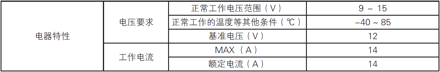
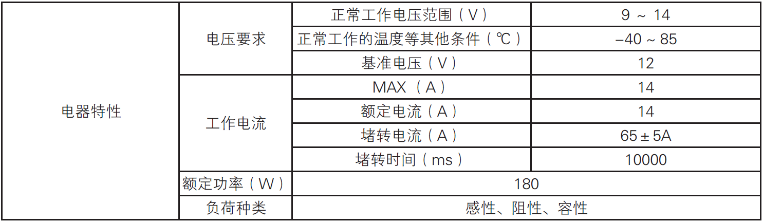
Technical parameters

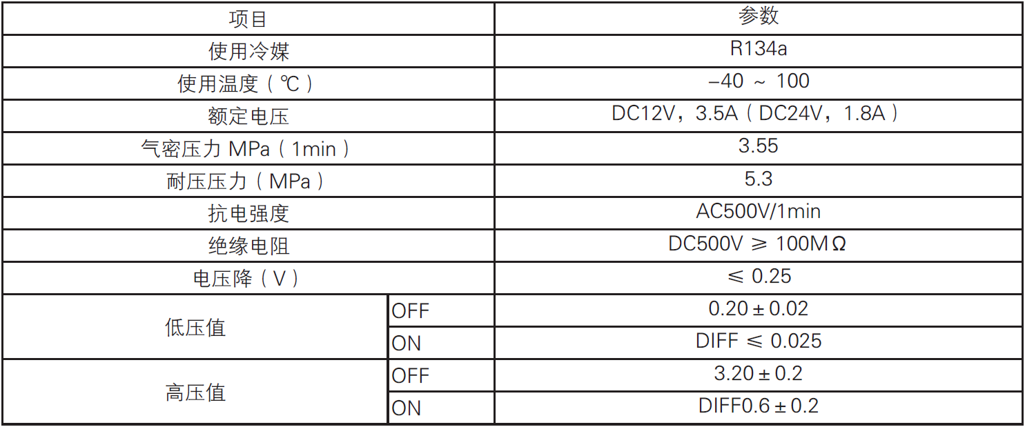
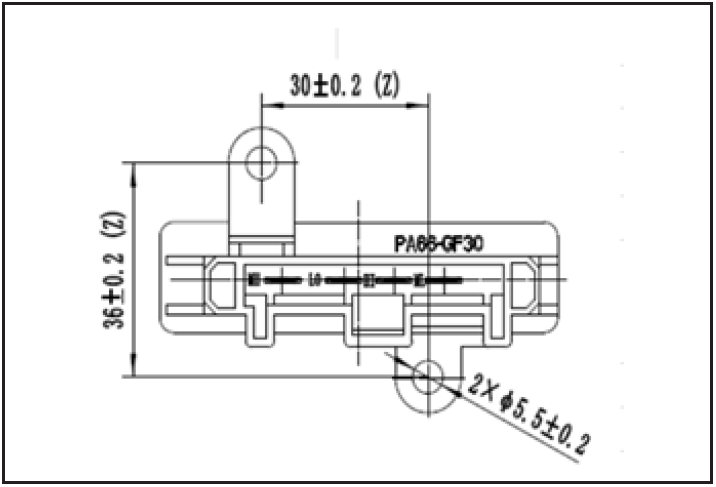
Basic parameters of electric air conditioning compressor
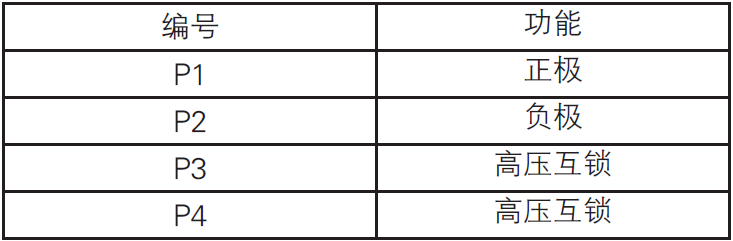
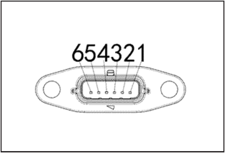
Pin definition of electric air conditioning compressor connector
Basic parameters of air conditioning pressure switch
Basic parameters of evaporator temperature sensor

Basic parameters of blower speed regulation module
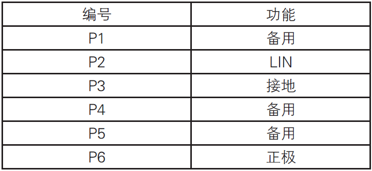
Pin definition of blower speed control module connector
Blower
Blower connector pin definition
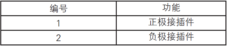
Tightening torque
Function description
Control panel description of electric air conditioner
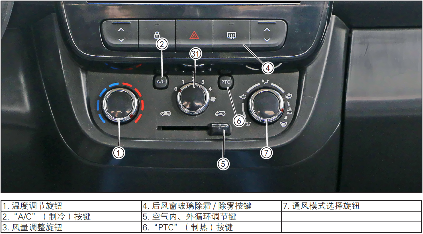
1. Temperature control knob
- Turn the knob and choose the appropriate temperature between the blue mark (cold air) and the red mark (hot air).
2. Air conditioning and refrigeration buttons
- Air conditioning can be used all the year round, and it can reduce the temperature in summer. Using air conditioner in winter can increase defogging efficiency. When using air conditioner, closing the window can achieve better results.
- Press the "A/C" air-conditioning refrigeration button, the green indicator light on the air-conditioning refrigeration button will light up, and the air-conditioning refrigeration function will be turned on.
- Press the "A/C" air conditioner refrigeration button again, the green indicator light on the air conditioner refrigeration button goes out, and the air conditioner refrigeration function is turned off.
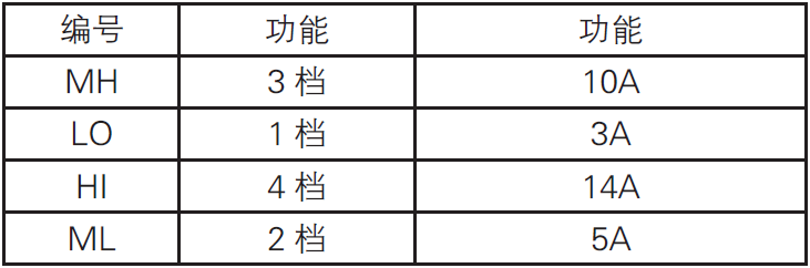
3. Fan control knob
- Turn the knob, from gear 1 to gear 4, and the air volume gradually increases.
4. Rear Windshield Defrost/Defogging Button
- When the vehicle key is in the "ACC" position, press the key, and the defrost/demister of the rear windshield can work. After pulling out the vehicle key, the working state will be remembered until the next time the air conditioner is turned on. The rear windshield defrost/mist eliminator is used to reduce moisture, fog and frost on the windshield surface to improve the driver's visual field.
- To turn off the demister manually, press the rear windshield demister button again.
注意!
- If the start switch is set to "OFF" before the demister/defroster automatically stops, the demister/defroster will continue after the vehicle starts again.
- Using the rear windshield defogging/defrosting function will increase the power consumption, which will lead to an increase in power consumption. Therefore, please stop the defogging/defrosting function in advance when conditions permit.
5. Air internal and external circulation adjustment keys
- By pressing the air inner circulation button to adjust the circulating air door, the conversion between air inner circulation and air outer circulation is realized.
注意!
- External circulation of air should be used as much as possible to avoid accumulation of turbid air and fogging of windows.
6. "PTC" button
To make the heater work and heat, the conditions are as follows:
If the indicator light on the air conditioner refrigeration button "A/C" lights up, press the air conditioner refrigeration button "A/C" at this time, the indicator light goes out and the air conditioner turns off refrigeration.
Press the air conditioning heating button "PTC", the indicator light on the button lights up, and turn the temperature adjustment knob to set the required temperature.
If the window is fogged, please use a demister instead of warm air.
7. Ventilation mode selection knob
 The airflow is mainly blown out from the front windshield wind and foot vents.
 The air flow is mainly blown out from the central, side and foot vents.
 The air flow is mainly blown out from the central and side vents.
 All the airflow blows out from the air outlet under the front windshield.
Fault diagnosis
Common fault diagnosis
1-The pressure of high pressure pipeline of refrigeration cycle system is too high
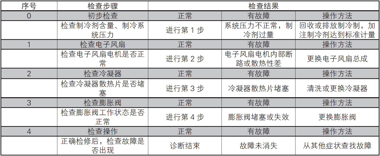
2-The pressure of low pressure pipeline of refrigeration cycle system is too high
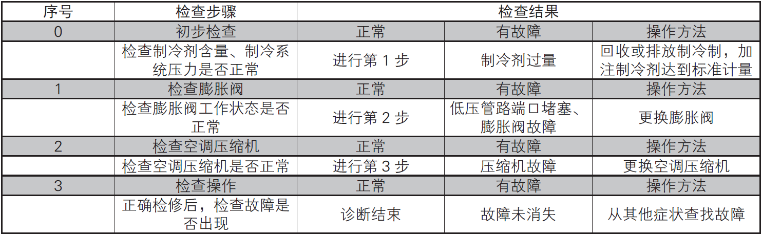
3-The pressure of low pressure pipeline of refrigeration cycle system is too low
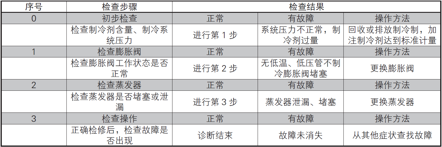
4-The pressure of high pressure pipeline of refrigeration cycle system is too low
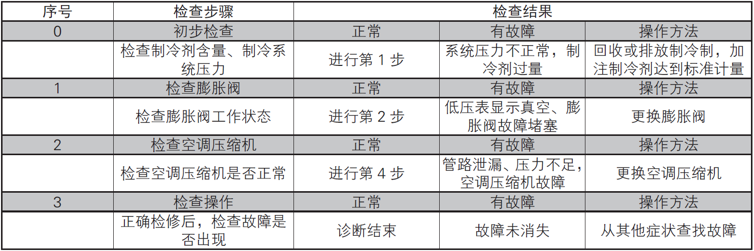
5-The air conditioner is not refrigerated
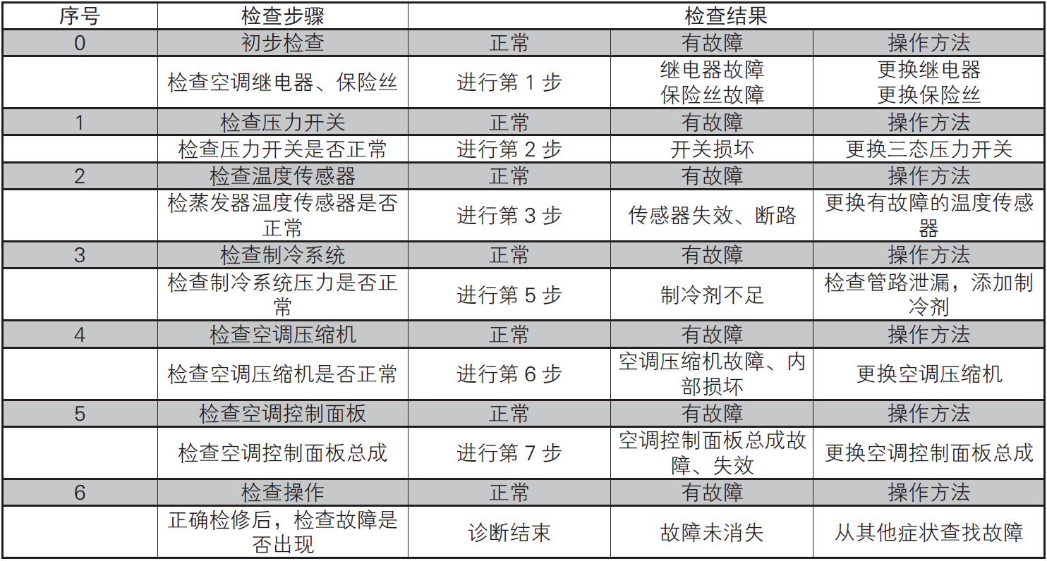
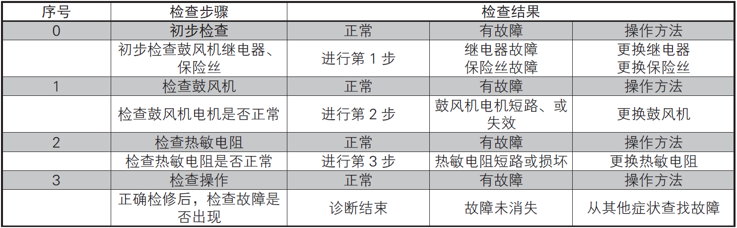
6-Air conditioning system without air supply
7-Insufficient refrigeration of air conditioner
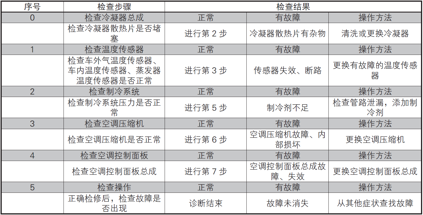
8-The condenser cooling fan has low speed and insufficient cooling performance
9-Air conditioning system compressor failure, low working efficiency
10-No warm air in air conditioning system
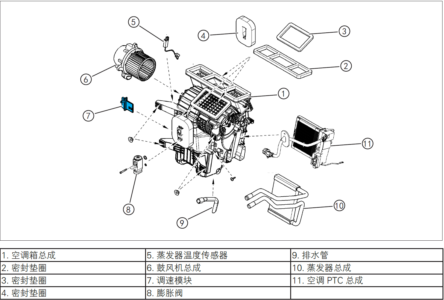
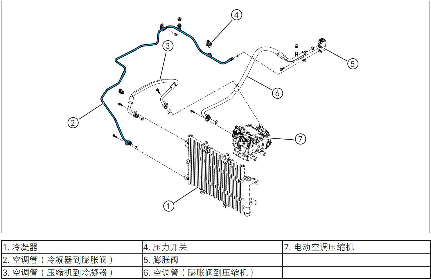
System overview
Structure and characteristics
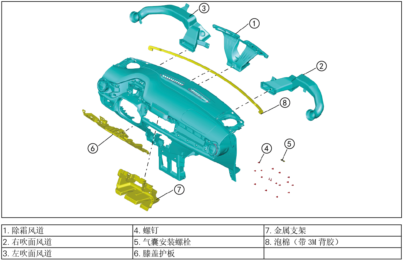
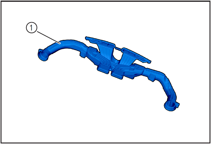
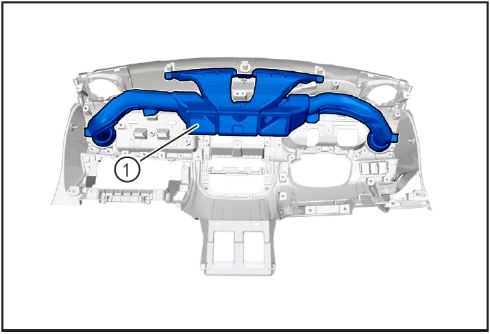
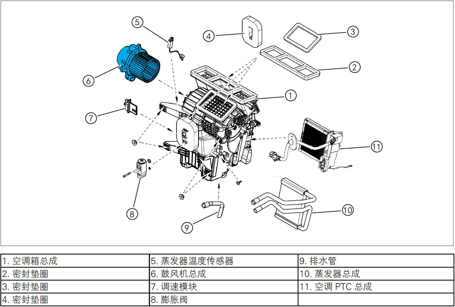
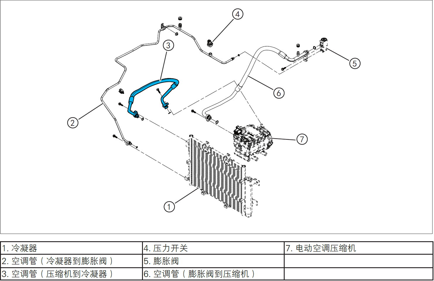
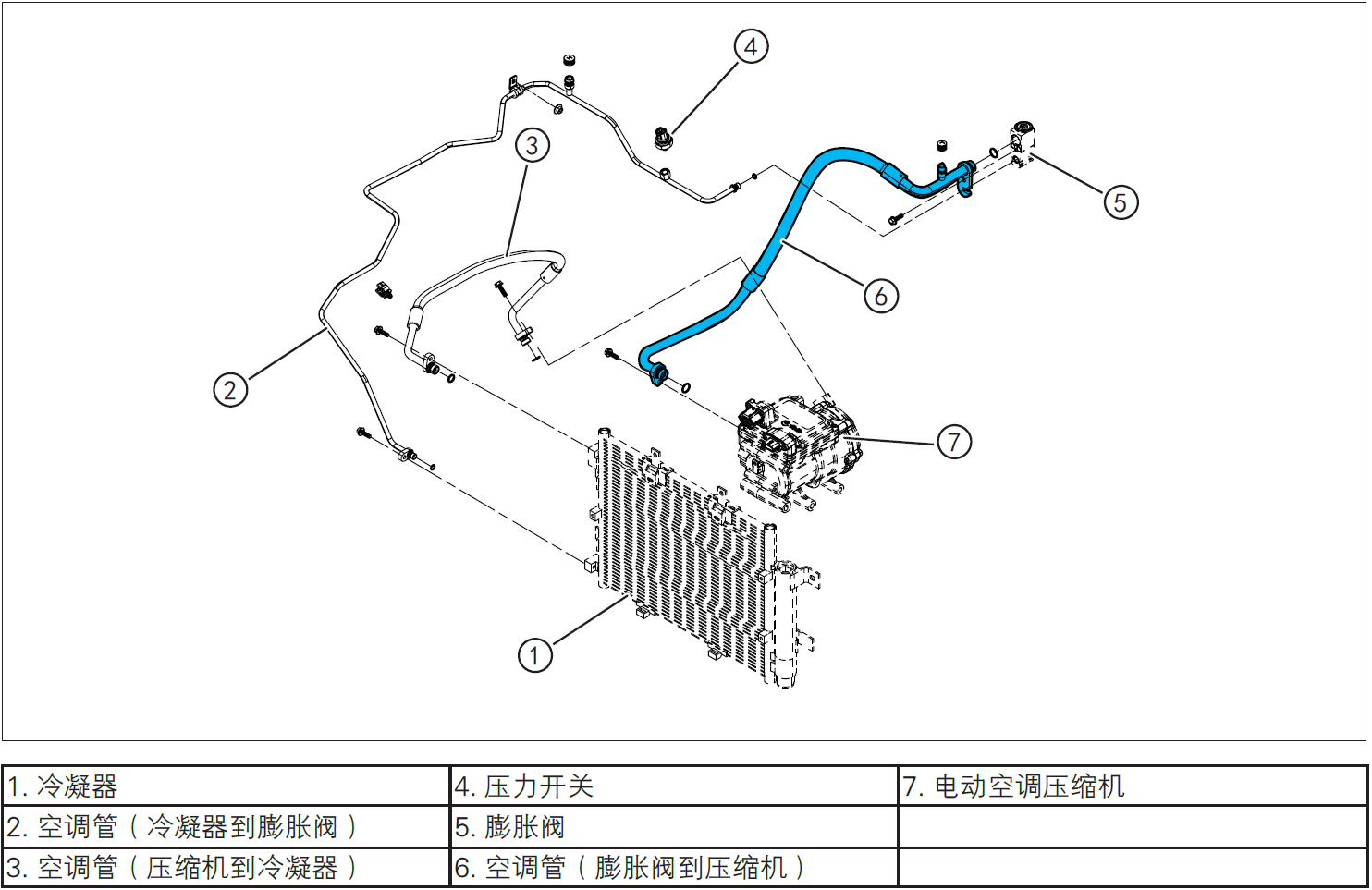
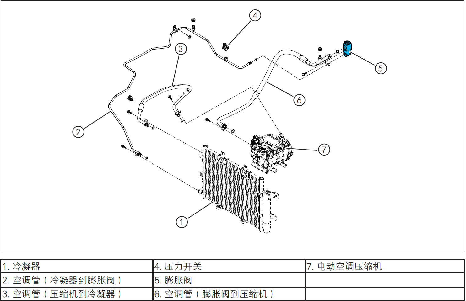
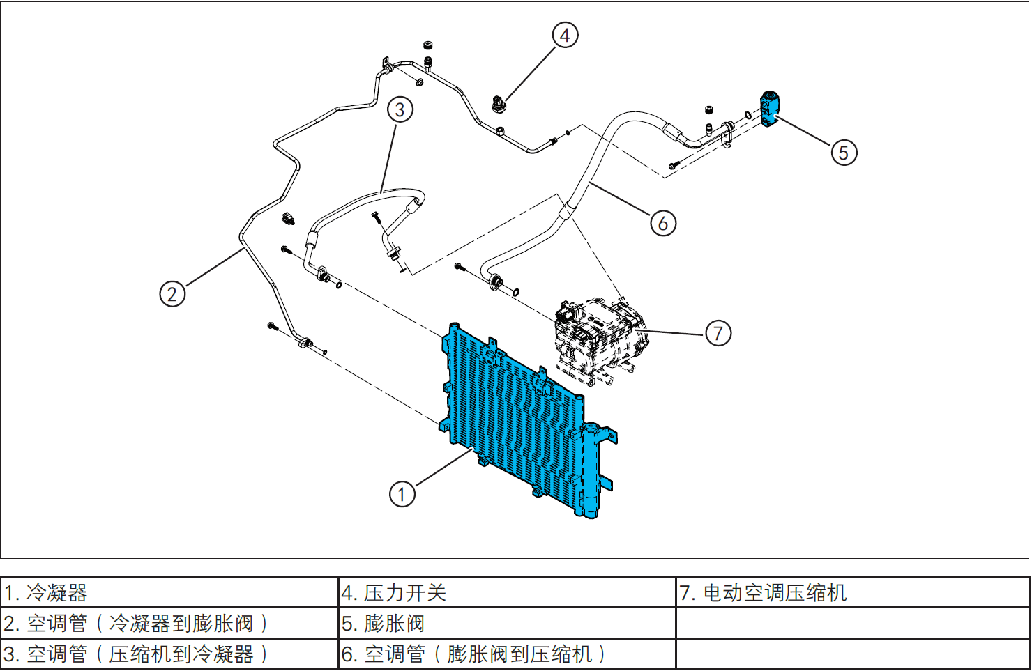
Air conditioning pipeline assembly
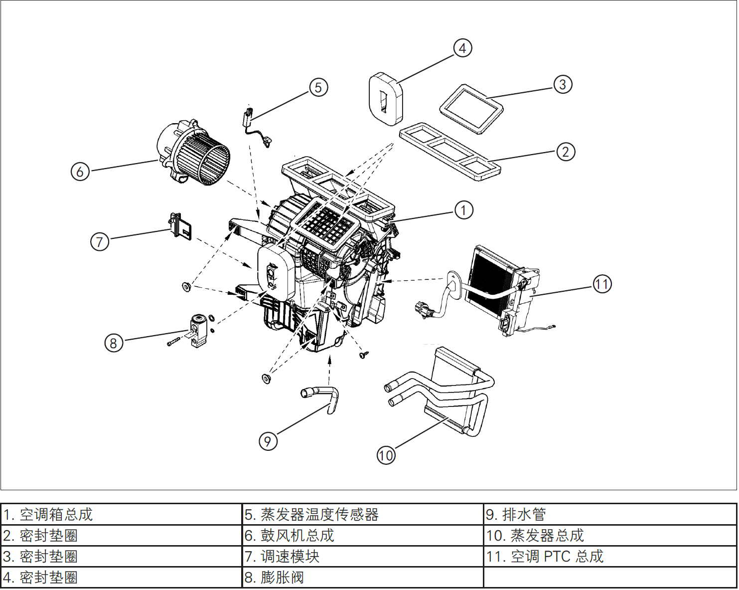
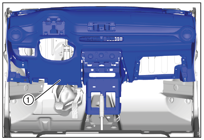
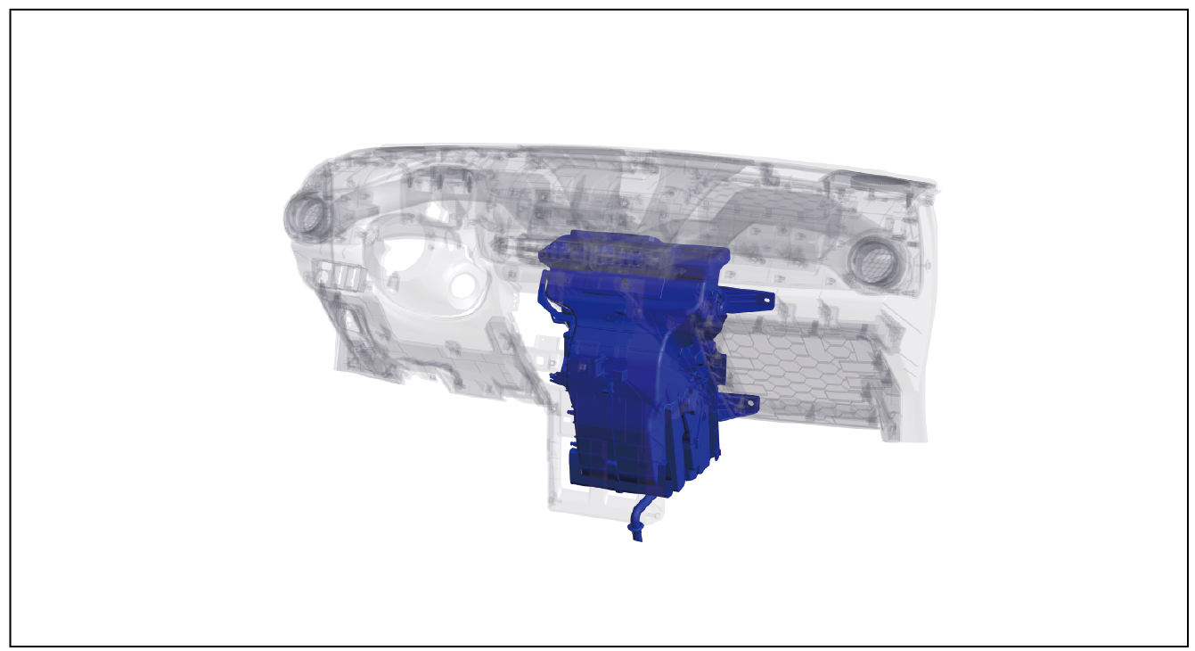
Air conditioning box assembly
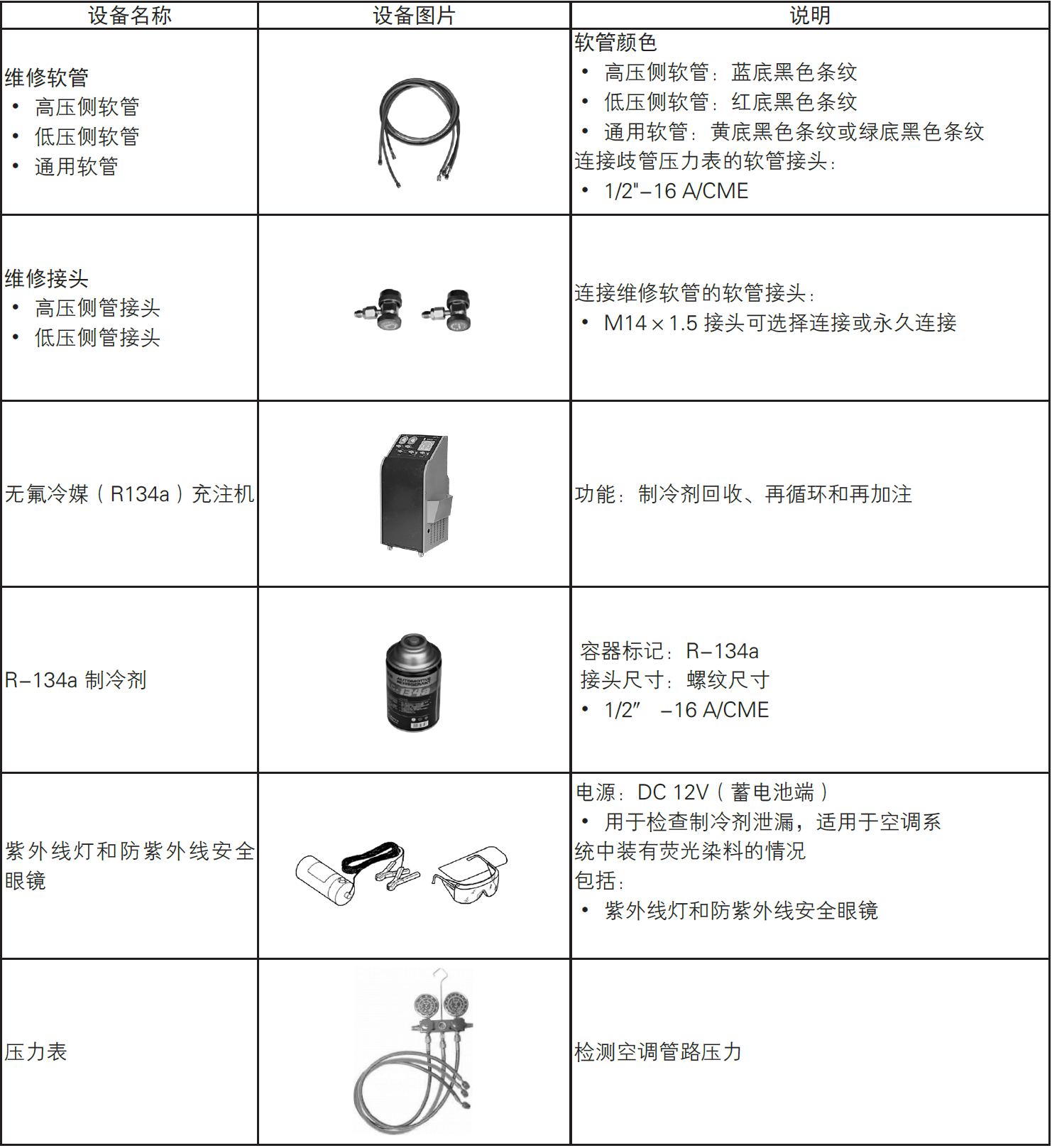
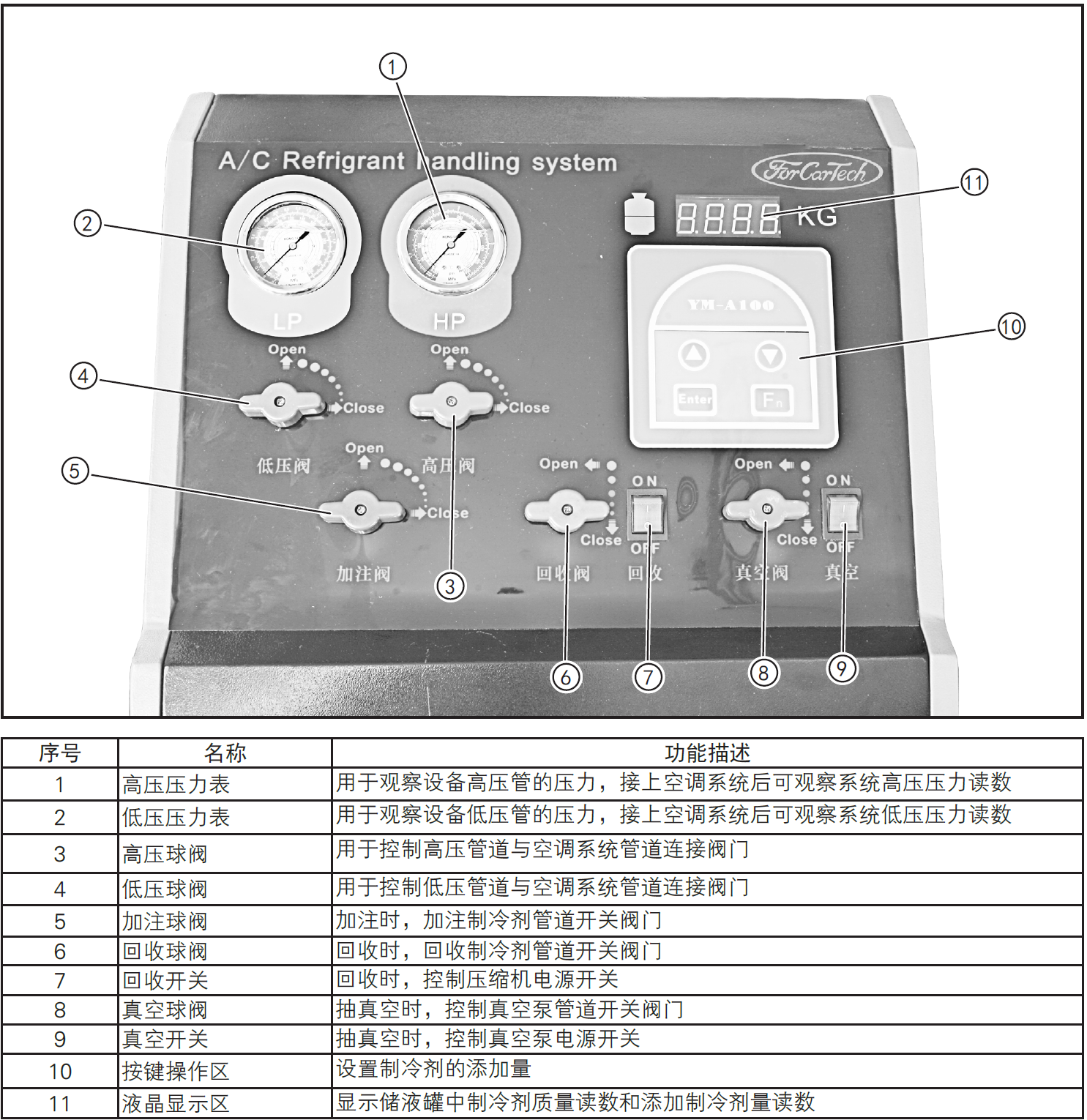
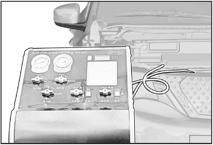
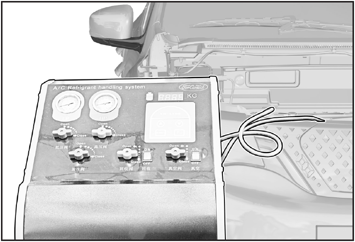
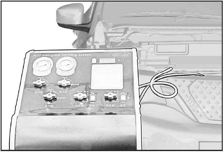
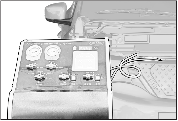
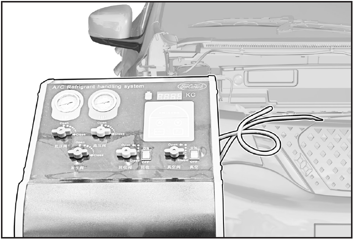
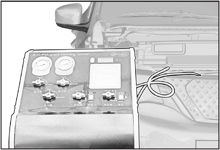
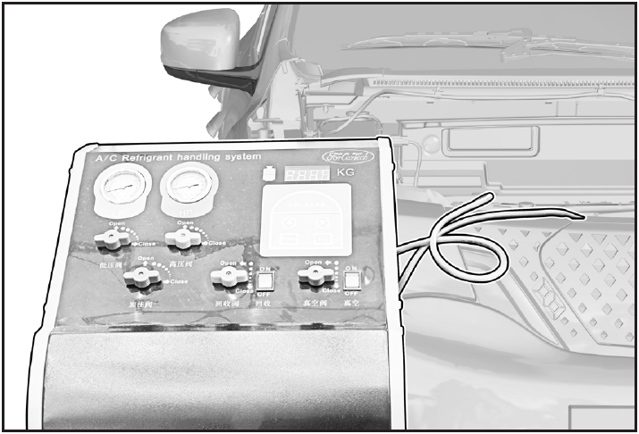
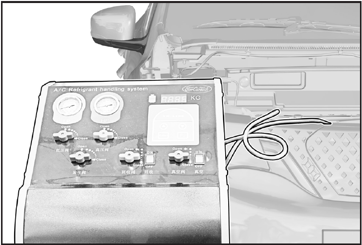
Instructions for operation of refrigerant (R-134a) charging and discharging machine
注意!
- The pressure vessel for storing R-134a refrigerant should not be overfilled to avoid explosion.
- Wear protective clothing when operating.
- Avoid using too long power cord.
- Replace the drying filter regularly.
- Check all joints and lines for leaks every three months.
- Keep away from gasoline or other combustibles when using this equipment.
Refrigerant Recovery/Vacuum Pumping/Pressure Holding/Filling/Leak Checking
Refrigerant recovery/vacuum pumping/pressure holding/filling
1-Protection

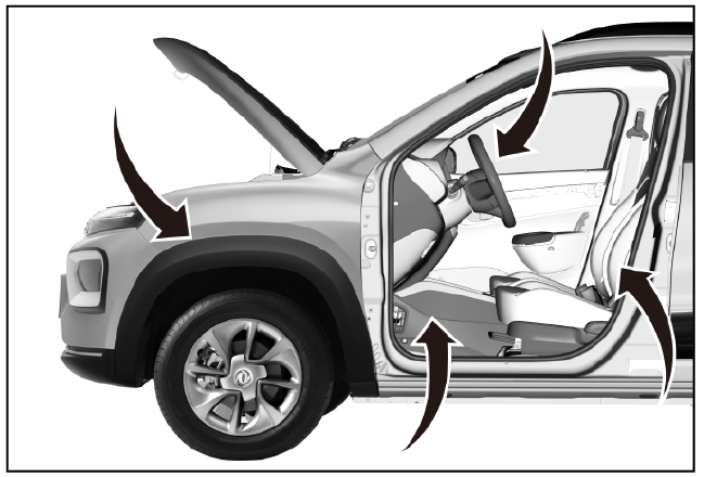
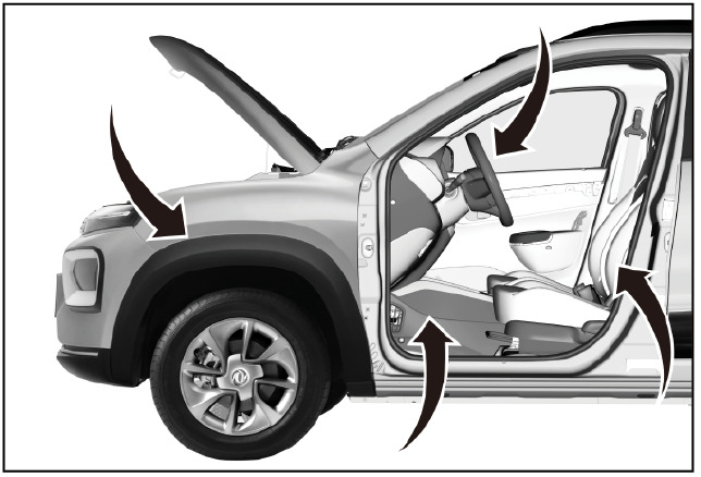
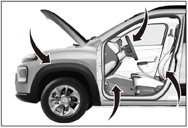
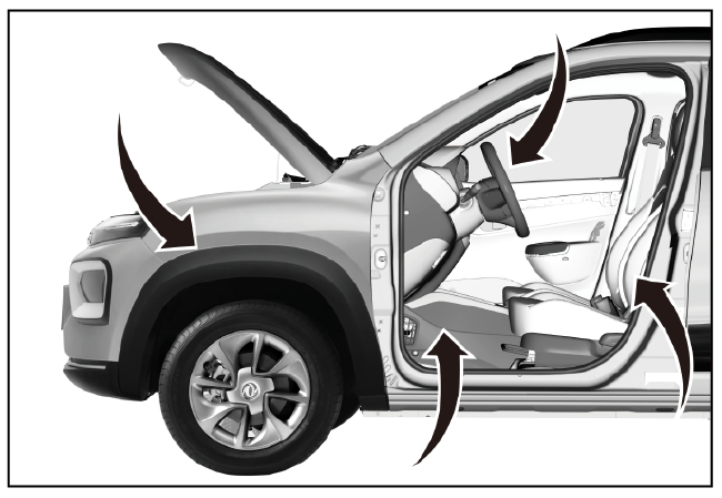
Place protective pads at the following positions:
- Front fender;
- Front bumper;
- Driver's seat;
- Carpet (driver's side);
- Steering wheel.
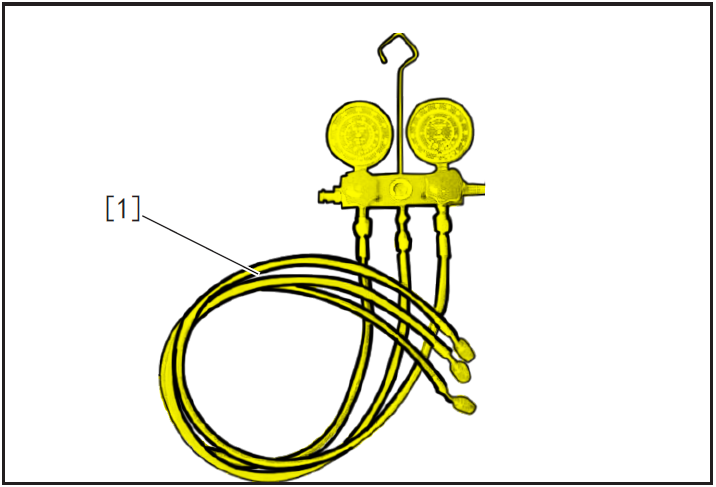
2-Recommended Tools
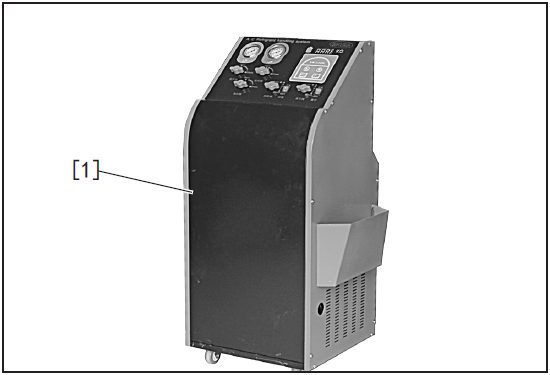
- Fluorine-free refrigerant (R-134a) filling machine [1].
警告!
- Air conditioning refrigerant and refrigerant oil vapor may irritate eyes, nose and throat. Be careful when connecting maintenance equipment. Do not inhale refrigerant and refrigerant oil vapor. Be sure to use maintenance equipment suitable for R-134a refrigerant.
- In order to prevent accidental leakage, ventilate the working area before maintenance work. Other health and safety information can be obtained from the instructions of refrigerant and refrigerant oil manufacturers.
- Operate in the parking state.
- When operating the equipment, use the fluorine-free refrigerant charging machine according to the safety manual provided by the equipment manufacturer and the safe electricity consumption rules in the workshop.
3-Refrigerant recovery
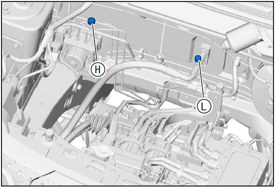
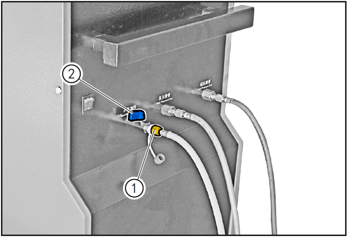
- Clean the dust cover of high and low pressure service valve and the pipeline around air conditioner.
- Remove the dust cover of the high and low pressure service valve.
- Description: The diameters of high pressure valve and low pressure valve are different and the dust cover is marked.
- H is the high pressure service valve, L is the low pressure service valve.
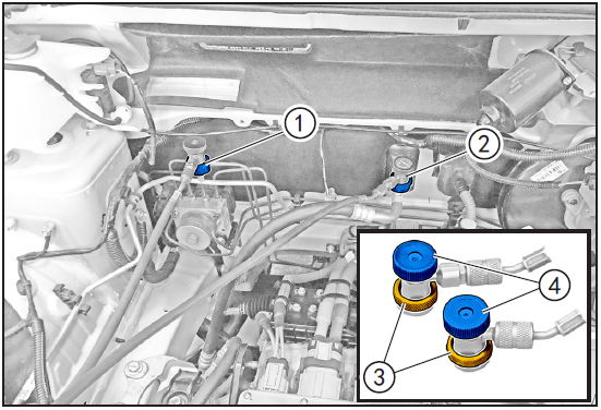
- Note: Red is the joint ① of high-pressure filling valve. Blue is the low pressure filling valve joint ②.
- Slide the locking ring ③ of the high-pressure filler coupling and the low-pressure filler coupling upwards, buckle them to the high-pressure service valve and the low-pressure service valve respectively, and loosen the locking ring ③ to connect them to the high-pressure service valve and the low-service pressure valve.
- Turn the knobs of the high-pressure filler pipe joint and the low-pressure filler pipe joint clockwise to connect the equipment pipeline with the air-conditioning pipeline.
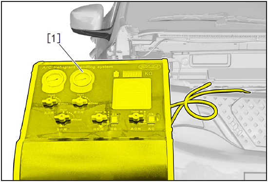

- Turn on the power switch of the fluorine-free refrigerant charging machine [1].
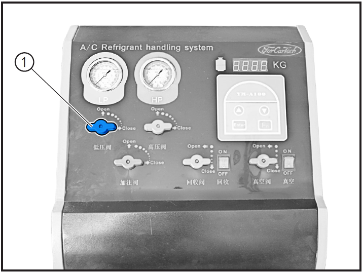
- Fully open low pressure ball valve ①, high pressure ball valve ② and recovery ball valve ③ counterclockwise, and then open recovery switch ④.
- The compressor that recovers refrigerant to the charging machine automatically stops, and closes the low pressure ball valve ①, high pressure ball valve ② and recovery ball valve ③ clockwise, and closes the recovery switch.
注意!
- When recovering, open the low pressure ball valve until the pressure drops, and then open the high pressure valve, so as to avoid the damage of the instrument caused by excessive refrigerant pressure at the beginning.
- The maximum amount of refrigerant recovered is 10kg. Please do not recover more than the specified value, so as not to cause instrument failure.
4-Refrigeration oil recovery
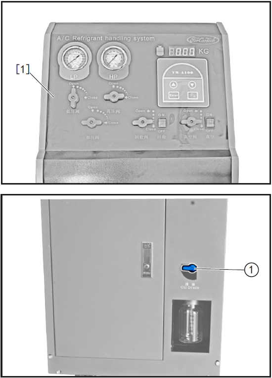
- Close all ball valves on [1] panel of fluorine-free refrigerant charging machine.
- Open the oil drain valve ① until the refrigerant oil is drained.
注意!
- After the refrigerant oil is recovered, check the residual pressure in the loop. If it is equal to 0, there is moisture infiltration problem in the operation of the air conditioning loop, and the air conditioning system should be checked.
5-Vacuum pumping and pressure holding
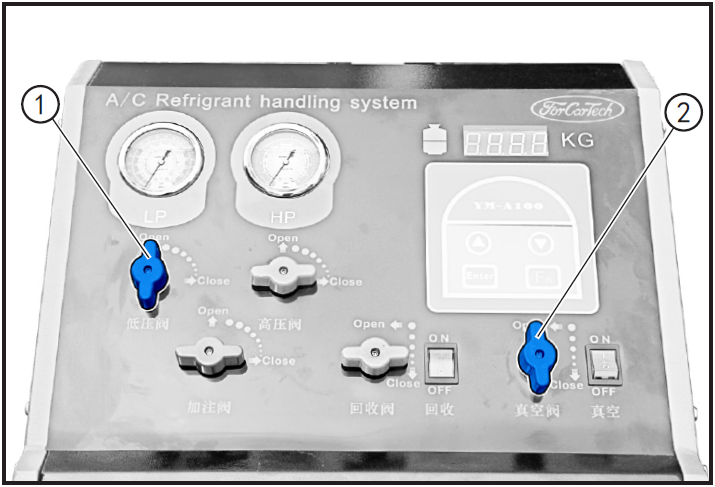
- Open the low pressure valve counterclockwise.
- Open vacuum ball valve ② and vacuum switch ③ counterclockwise.
- Observe the low pressure gauge reading until the pressure gauge reading is less than-20psi, then close the vacuum ball valve counterclockwise and close the vacuum switch.
- After vacuumizing, check whether the pressure of the air-conditioning system rises. If so, there is leakage in the air-conditioning system, so the air-conditioning system should be detected for leakage and troubleshooting. (Refer to "Leak Detection of Air Conditioning Systems")
注意!
- The continuous working time of vacuum pump cannot exceed 30 minutes, otherwise the vacuum pump is easy to be damaged.
6-Refrigeration oil addition
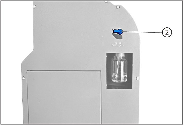
- Open the low pressure ball valve ① and refueling valve ② to manually adjust the filling amount of refrigerant oil.
注意!
- When there is moisture leakage problem in the operation of air conditioning circuit and it is eliminated, 80ml new refrigerant oil should be filled into air conditioning pipeline at the same time of filling refrigerant.
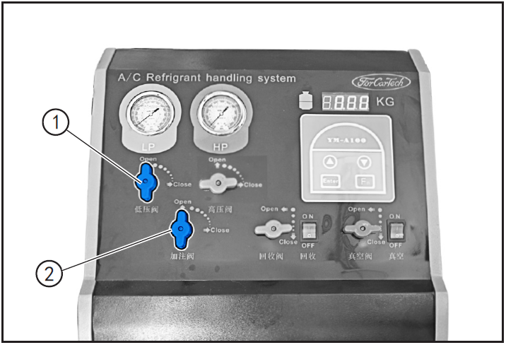
7-Refrigerant filling
注意!
- After closing the low-pressure and high-pressure control valves, wait for 5 minutes, and then confirm that the pointer has not changed before filling operation. If the pointer changes, check the pipeline and joint for leaks, repair the defective parts, and then proceed to the following operation.
Fill with fluorine dispenser
- Press the "Enter" key, adjust the refrigerant filling amount through "" and ", and then press the" Enter "key to confirm.
- Open the low pressure ball valve ① and the filling ball valve ② for refrigerant filling.
- Close the low pressure ball valve and filling valve after filling.
- Remove high-pressure filler valve connector and low-pressure filler valve connector.
- Install the dust cover of the service valve on the air conditioning line.
注意!
- The refrigerant in the liquid storage tank should be greater than 1kg weight, so as to avoid too little refrigerant to be filled.
- When the internal pressure of the equipment is too low and the refrigerant cannot be completely added, the low-pressure control valve can be opened, the high-pressure control valve can be closed and the vehicle can be started to fully add the refrigerant.
- After removing the high-pressure filler valve joint and the low-pressure filler valve joint, pour soapy water into the high-pressure and low-pressure maintenance valve on the air-conditioning pipeline to observe whether there are bubbles. If there is, it shows that there is leakage here. The valve core must be tightened with the air-conditioning valve core tool to confirm that there is no leakage again. If there is no leakage, the soapy water in the high-pressure and low-pressure maintenance valves must be blown out with compressed air.
Fill with small cans of refrigerant
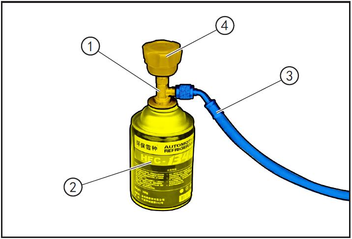
- Connect bottle opener ① with refrigerant tank ②.
- Connect bottle opener ① to refrigerant filling pipe ③.
- Turn the manual valve ④ of bottle opener ① clockwise to the end, so that the needle valve of bottle opener retreats to the top.
- Loosen the end of refrigerant filling pipe ①, exhaust the air in the filling pipe, and then tighten the end of the filling pipe.
- Open the vial filling ball valve ② and fill the refrigerant.
- After filling, remove the high-pressure filler valve joint and the low-pressure filler valve joint.
- Install the dust cover of the service valve on the air conditioning line.
注意!
- When the internal pressure of the equipment is too low and the refrigerant cannot be completely added, the low-pressure control valve can be opened, the high-pressure control valve can be closed and the vehicle can be started to fully add the refrigerant.
- After removing the high-pressure filler valve joint and the low-pressure filler valve joint, pour soapy water into the high-pressure and low-pressure maintenance valve on the air-conditioning pipeline to observe whether there are bubbles. If there is, it shows that there is leakage here. The valve core must be tightened with the air-conditioning valve core tool to confirm that there is no leakage again. If there is no leakage, the soapy water in the high-pressure and low-pressure maintenance valves must be blown out with compressed air.
Leak detection of air conditioning system
1-Protection
Place protective pads at the following positions:
- Front fender;
- Front bumper;
- Driver's seat;
- Carpet (driver's side);
- Steering wheel.
警告!
- Read carefully and master the notes in this section (refer to "Notes" in this section) before proceeding to the next step.
2-Recommended Tools
- Manifold pressure gauge.
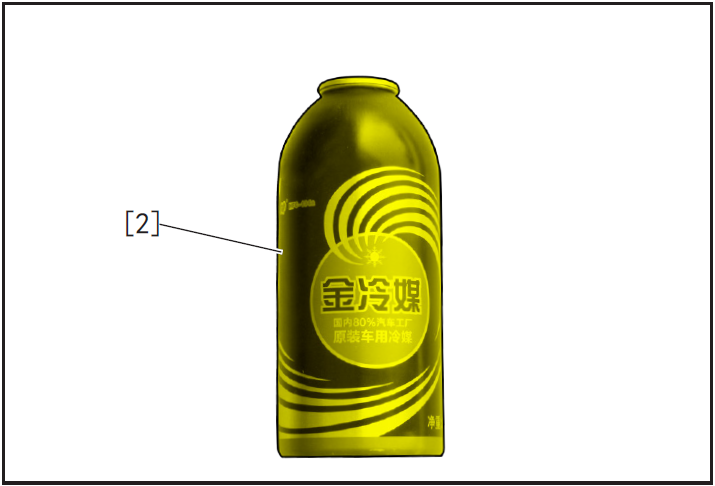
- Refrigerant containing fluorescent agent [2].
3-Operation
Soapy water leak detection
注意!
- When leak detection is carried out, the refrigerant is recovered/vacuumized first. (Refer to "Refrigerant Recovery/Vacuumizing/Holding Pressure/Filling/(Using Filling Machine)")
- Fill nitrogen into the air conditioning line through the manifold pressure gauge, and stop filling nitrogen when the manifold pressure gauge shows 1.00 Mpa.
- Apply soapy water to the joint of air-conditioning pipeline joint to observe whether there are bubbles. If so, remove air-conditioning pipeline components, replace their sealing rings or replace pipeline components.
注意!
- When checking for leaks, you should continue to search after finding one or two places until all joints are checked.
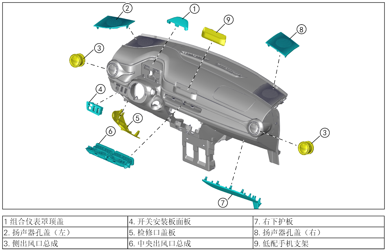
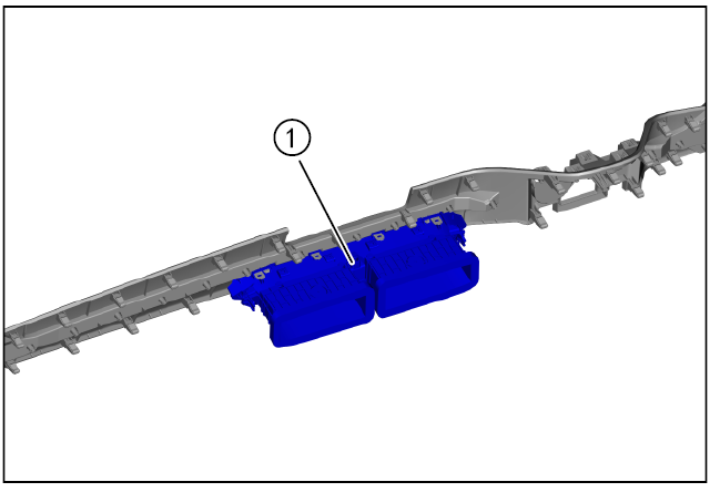
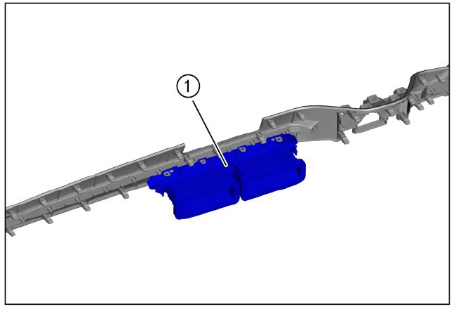
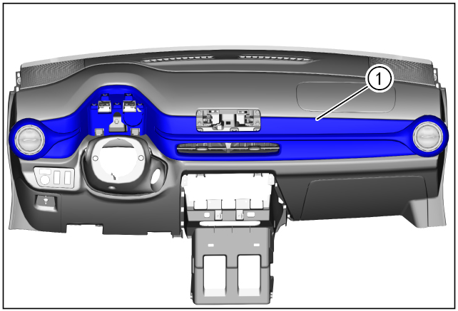
Air conditioning control panel
Disassembly and installation of air conditioning control panel
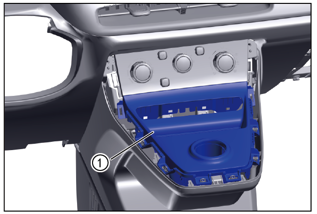
1-Part position
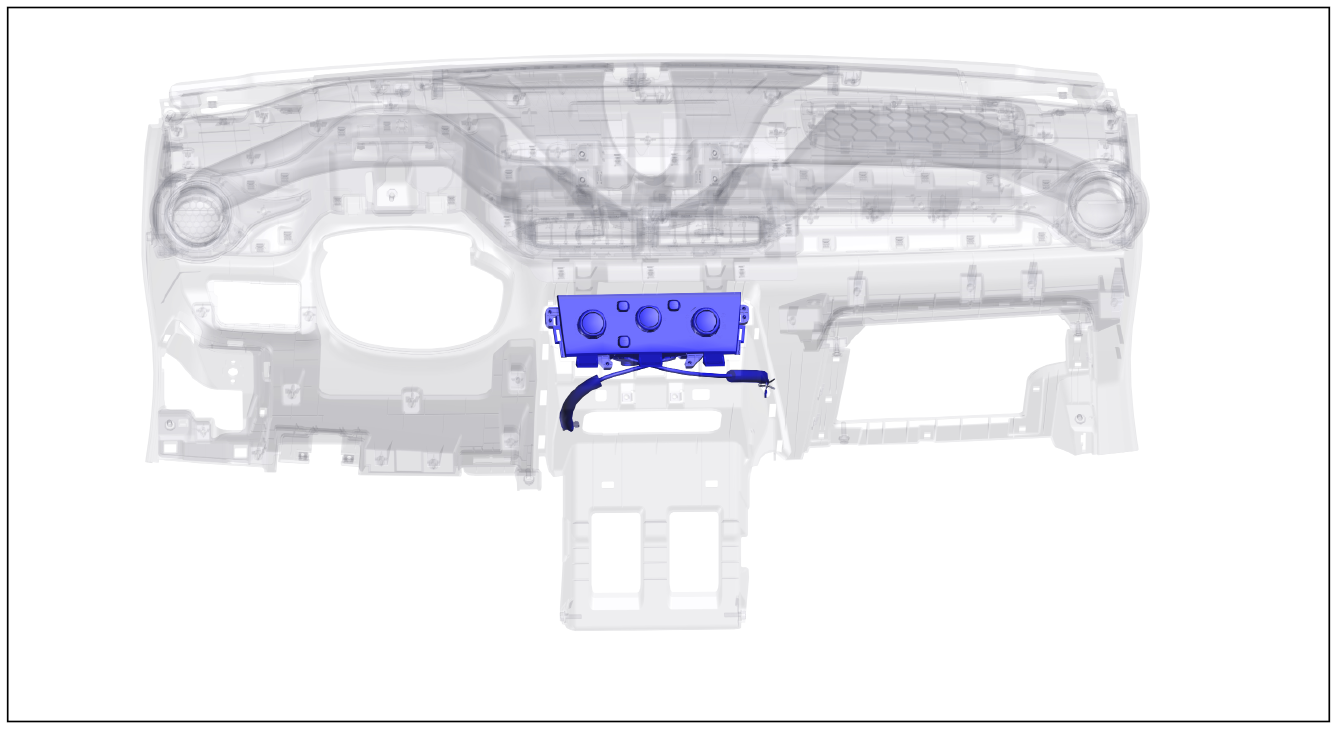
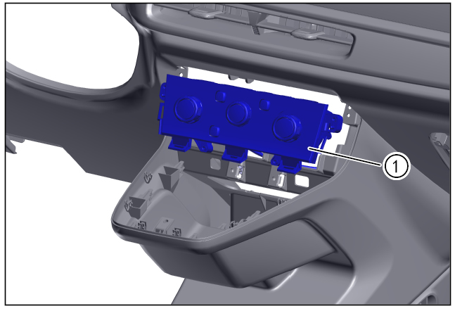
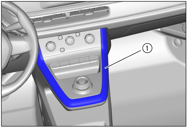
The air conditioning control panel is installed in the middle of the instrument panel
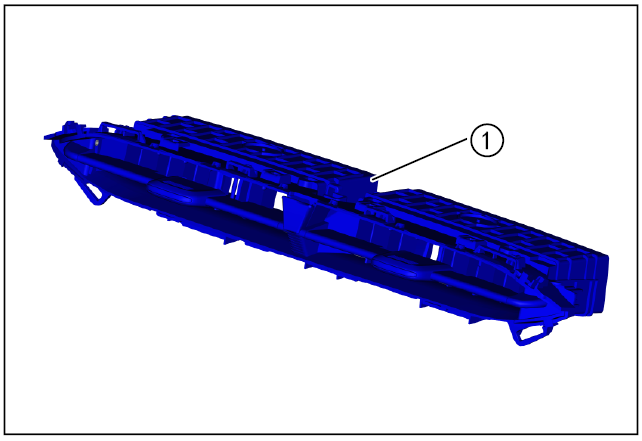
2-Component structure diagram
3-Protection
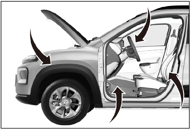
Place protective pads at the following positions:
- Front fender;
- Front bumper;
- Driver's seat;
- Carpet (driver's side);
- Steering wheel.
警告!
- Carefully read and master the maintenance precautions in this chapter (refer to "Precautions" in this chapter) before proceeding to the next operation.
4-Recommended Tools
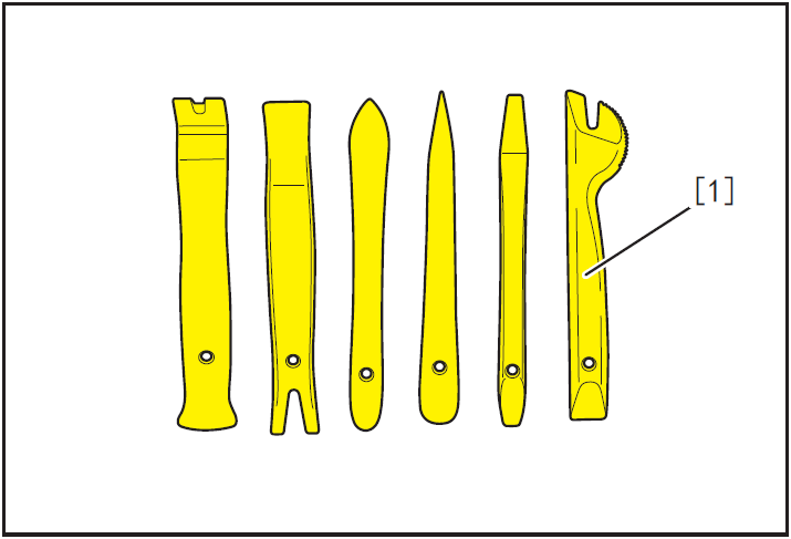
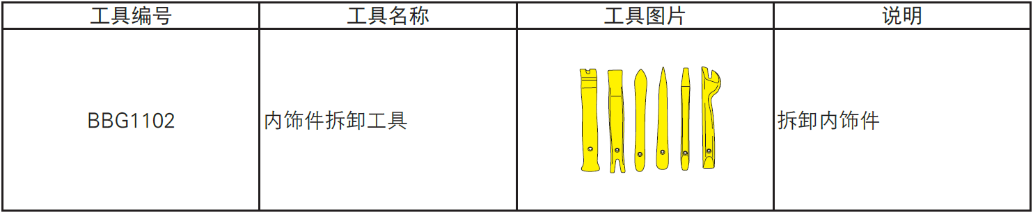
- Internals Removal Tool (BBG1102) [1].
5-Vehicle low voltage circuit locking
- Refer to "Vehicle Low Voltage Circuit Locking and Unlocking" in the chapter "Power Battery System" for the following operation
Vehicle ECU dormancy

- Register electric vehicle information, check instrument indicator light and sleep ECU.
Disconnect the positive and negative cables of the battery

- Disconnect the negative cable ① and positive cable ② of the battery.
注意!
- After disconnecting the negative cable of the battery, pay attention to avoid short connection between positive and negative electrodes.
6-Remove
Removing trim strip for auxiliary instrument
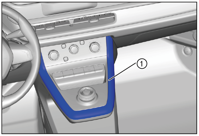
- Use the interior trim removal tool (BBG1102) to pry open along the periphery of the secondary gauge trim strip (1).
- Use the interior trim removal tool (BBG1102) to pry open around the shift trim panel (1)
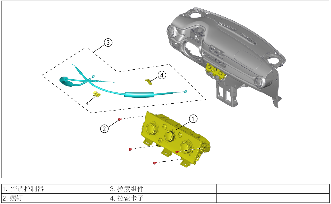
Removing air conditioning controller assembly
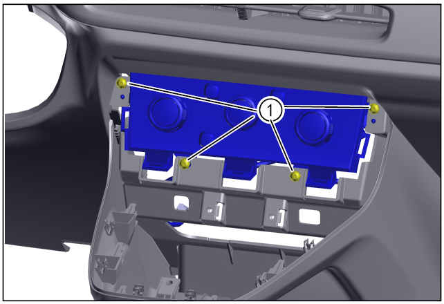
- Remove the 4 fixing screws (1) around the air conditioning controller using the T20 batch head.
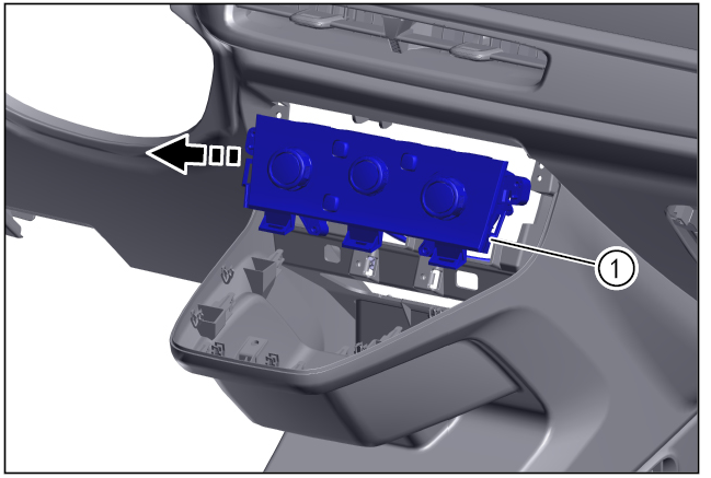
- Move out of the air conditioning control panel (1) in the direction of the arrow.
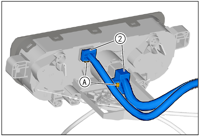
- Press and hold the air conditioning control panel switch connector locking clip (A) to disengage the air conditioning control panel connector (2).
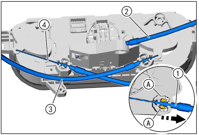
- Remove the cable (1) in the direction of the arrow, adjust the position of the cable, and take out the cable with the aid of disconnecting the cable limit card (A).
- The indoor and outdoor circulating cables (2), the temperature control cables (3) and the air outlet adjusting cables (4) are disassembled by the above method.
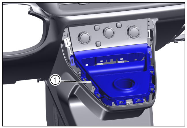
- Remove air conditioning control panel.
7-Check
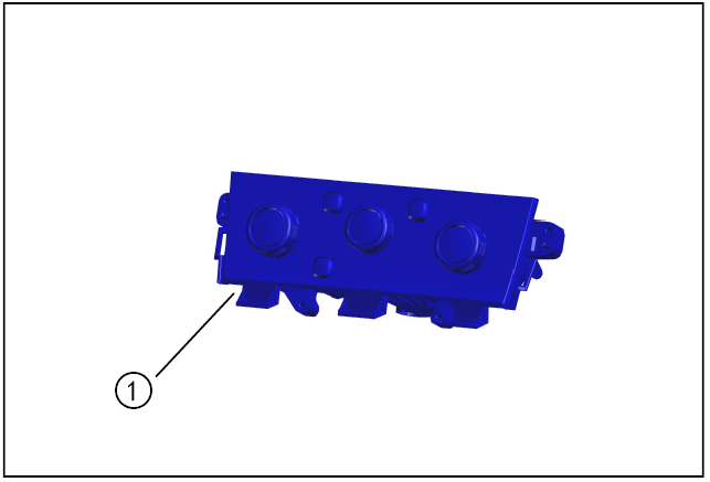
- Check whether the air-conditioning control panel ① is damaged, check whether the air-conditioning control knob is stuck, and if so, replace the new air-conditioning control panel.
8-Installation
Installing air conditioning control panel
- Place the air conditioning control panel ① to the installation position.
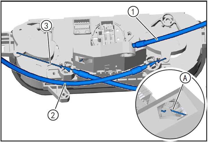
- Arrange the air conditioning control panel cables and align the air conditioning control panel cables with the corresponding operators.
- Pass the air conditioning control panel cable pin (A) through the operator and clip the cable into the limit card.
- Install indoor and outdoor circulating cables ①, temperature control A-made cables ② and air outlet adjustment cables ③ by the above methods.

- Install switch connector ① of air conditioning control panel until "click" sound is heard and installed in place.
- Install 4 fixing screws of air conditioning control panel ① with T20 batch head ② and tighten them with tightening torque of 4N m.
Installing shift trim panel
- Install shift trim panel (1) retaining card aligned with secondary dashboard in place.
- Align the secondary dashboard trim strip (1) retaining card with the secondary dashboard and install it in place.
9-Vehicle low voltage circuit unlock
- Refer to "Vehicle Low Voltage Circuit Locking and Unlocking" in the chapter "Power Battery System" for the following operation
Install battery positive and negative cables

- Install battery negative cable ① and positive cable ②.
10-Clear fault code, check
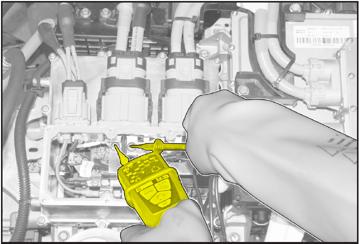
- After installation, turn the ignition switch to "ON", connect the diagnostic instrument, and clear the fault code.
- Check and confirm that the switch function of air conditioning panel is normal.
- Remove safety warning fences and warning signs.
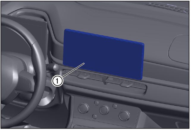
Air conditioning vent
Disassembly and installation of front central air outlet
1-Part position
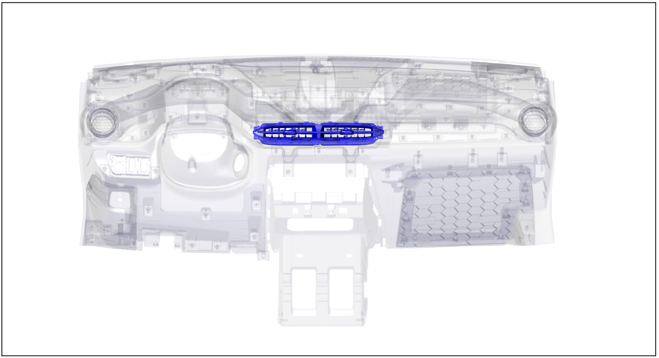
The front central air outlet is installed on the inner side of the middle of the instrument panel
2-Component structure diagram
3-Protection

Place protective pads at the following positions:
- Front fender;
- Front bumper;
- Driver's seat;
- Carpet (driver's side);
- Steering wheel.
警告!
- Carefully read and master the maintenance precautions in this chapter (refer to "Precautions" in this chapter) before proceeding to the next operation.
4-Recommended Tools
- Internals Removal Tool (BBG1102) [1].
5-Vehicle low voltage circuit locking
- Refer to "Vehicle Low Voltage Circuit Locking and Unlocking" in the chapter "Power Battery System" for the following operation
Vehicle ECU dormancy

- Register electric vehicle information, check instrument indicator light and sleep ECU.
Disconnect the positive and negative cables of the battery
- Disconnect the negative cable ① and positive cable ② of the battery.
注意!
- After disconnecting the negative cable of the battery, pay attention to avoid short connection between positive and negative electrodes.
6-Remove
Removing display screen of audio-visual entertainment system
- Remove the entertainment display (1). (Refer to "Audio and Video Entertainment System Assembly Removal and Installation" under "Audio and Telephone Systems")
- Remove instrument cluster (1). (Refer to "Instrument Cluster Removal and Installation" in "Driver Information System").
- Remove the instrument panel trim panel assembly (1) using the interior trim removal tool (BBG1102).
Removing front central air outlet
- Use the interior trim removal tool (BBG1102) to pry open around the air outlet and remove the central air outlet.
7-Check
- Check whether the front central air outlet 8-installation port ① is damaged. If so, replace the front central air outlet with a new one.
8-Installation
Installing front central air outlet
- Position the front central air outlet (1) to the installation position.
- Position the instrument panel trim panel assembly (1) into the installation position.

- Install instrument cluster (1). (Refer to "Instrument Cluster Removal and Installation" in "Driver Information System".

- Install the entertainment display (1). (Refer to "Audio and Video Entertainment System Assembly Removal and Installation" under "Audio and Telephone Systems")
9-Vehicle low voltage circuit unlock
- Refer to "Vehicle Low Voltage Circuit Locking and Unlocking" in the chapter "Power Battery System" for the following operation
Install battery positive and negative cables

- Install battery negative cable ① and positive cable ②.
10-Clear fault code, check
- After installation, turn the ignition switch to "ON", connect the diagnostic instrument, and clear the fault code.
- Check and confirm that the central control panel is functioning normally.
- Remove safety warning fences and warning signs.
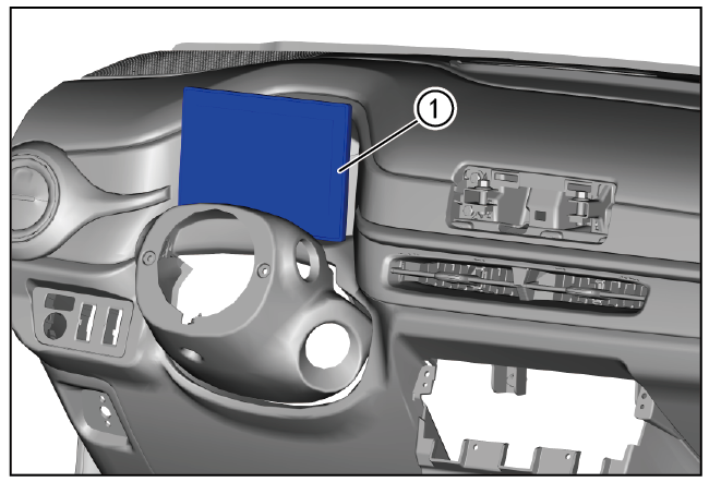
Disassembly and installation of front exhaust duct
1-Part position
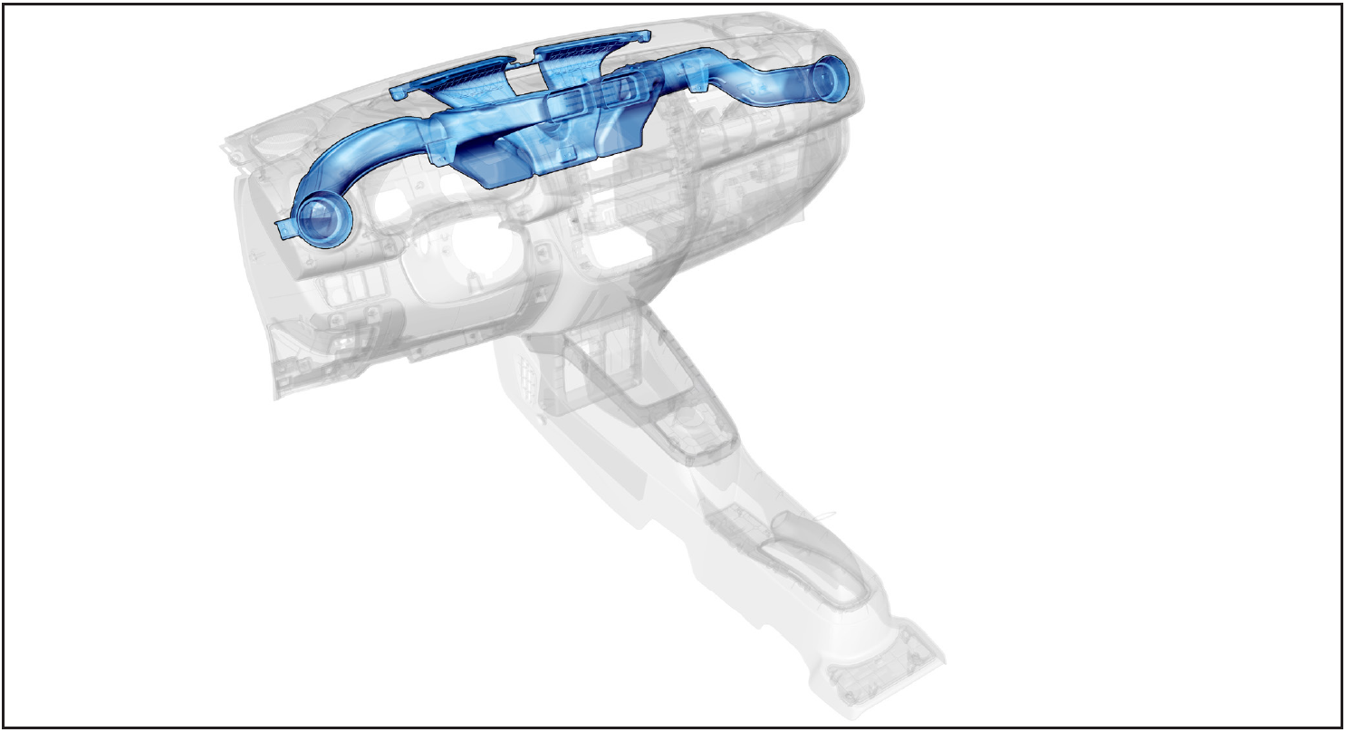
The front exhaust duct is installed on the inner side of the instrument panel
2-Component structure diagram
3-Protection

Place protective pads at the following positions:
- Front fender;
- Front bumper;
- Driver's seat;
- Carpet (driver's side);
- Steering wheel.
警告!
- Carefully read and master the maintenance precautions in this chapter (refer to "Precautions" in this chapter) before proceeding to the next operation.
4-Vehicle low voltage circuit locking
- Refer to "Vehicle Low Voltage Circuit Locking and Unlocking" in the chapter "Power Battery System" for the following operation
Vehicle ECU dormancy
- Register electric vehicle information, check instrument indicator light and sleep ECU.
Disconnect the positive and negative cables of the battery

- Disconnect the negative cable ① and positive cable ② of the battery.
注意!
- After disconnecting the negative cable of the battery, pay attention to avoid short connection between positive and negative electrodes.
5-Remove
Removing instrument panel assembly

- Remove the instrument panel assembly ①. (Refer to "Instrument Panel Assembly Removal and Installation" in "Instrument Panel" section)
Remove the outlet duct assembly
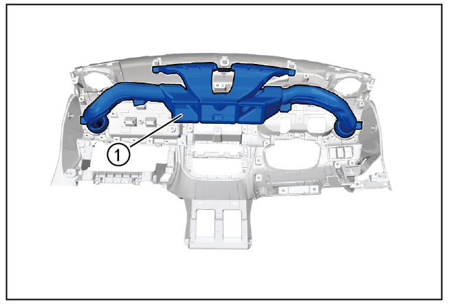
- Use T20 batch head to remove 10 fixing screws of air duct and remove air duct ①.
6-Check
- Check whether the front row 7-installed outlet duct ① is damaged or blocked. If so, replace the front outlet duct with a new one.
7-Installation
Install the air outlet assembly
- Align the front discharge duct ① with the mounting hole on the instrument panel, bring in the 10 fixing screws and tighten using the T20 batch head.
Installing the instrument panel assembly
- Install the instrument panel assembly ①. (Refer to "Instrument Panel Assembly Removal and Installation" in "Instrument Panel" section)
8-Vehicle low voltage circuit unlock
- Refer to "Vehicle Low Voltage Circuit Locking and Unlocking" in the chapter "Power Battery System" for the following operation
Install battery positive and negative cables

- Install battery negative cable ① and positive cable ②.
9-Clear fault code, check
- After installation, turn the ignition switch to "ON", connect the diagnostic instrument, and clear the fault code.
- After the installation is completed, turn on the air conditioner, and check and confirm that the air volume of each air outlet is normal.
- Remove safety warning fences and warning signs.
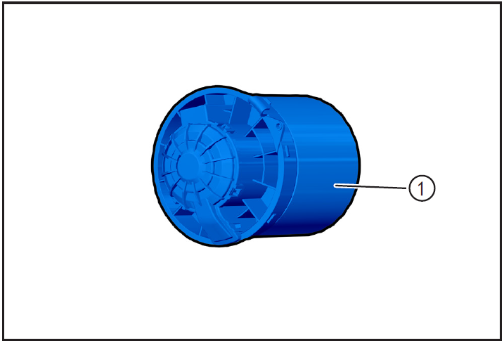
Air conditioner blower
Disassembly and installation of blower assembly
1-Part position
The blower assembly is installed on the inner side of the instrument panel and beside the glove box
2-Component structure diagram
3-Protection
Place protective pads at the following positions:
- Front fender;
- Front bumper;
- Driver's seat;
- Carpet (driver's side);
- Steering wheel.
警告!
- Carefully read and master the maintenance precautions in this chapter (refer to "Precautions" in this chapter) before proceeding to the next operation.
4-Vehicle low voltage circuit locking
- Refer to "Vehicle Low Voltage Circuit Locking and Unlocking" in the chapter "Power Battery System" for the following operation
Vehicle ECU dormancy

- Register electric vehicle information, check instrument indicator light and sleep ECU.
Disconnect the positive and negative cables of the battery
- Disconnect the negative cable ① and positive cable ② of the battery.
注意!
- After disconnecting the negative cable of the battery, pay attention to avoid short connection between positive and negative electrodes.
5-Remove
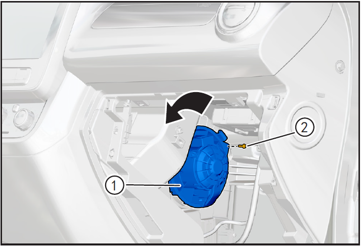
Removing blower assembly
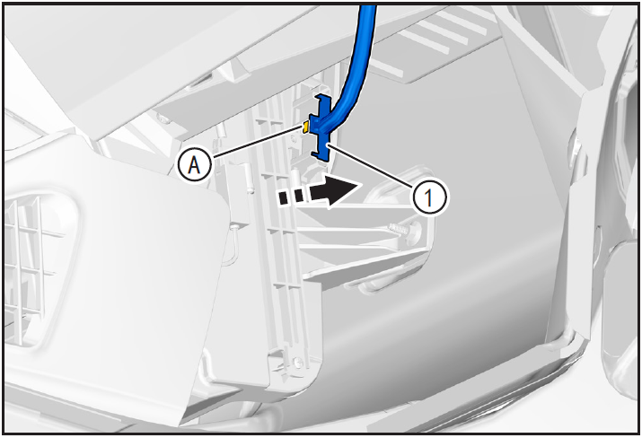
- Press and hold the blower assembly connector lock card (A) and disengage the blower assembly connector ①.
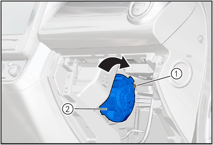
- Remove the blower assembly fixing screw ① using the cross lift and rotate clockwise in the direction of the arrow to remove the blower assembly ②.
6-Check
- Check the blower assembly ①, rotate the impeller gently, and check whether there are cracks on the outer end face, outer ring and blade surface of the impeller. It is required that there should be no cracks on the surface of the above positions. Once found, a new blower should be replaced for installation.
- Check whether the blower runs smoothly and without noise. If there is noise in operation, replace it with a new blower for installation.
7-Installation
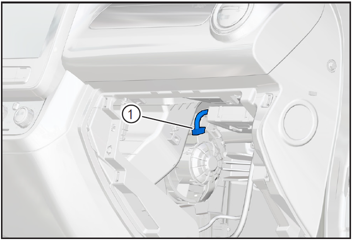
Installing blower assembly
- Put the blower assembly ① to the installation position, rotate counterclockwise in the direction of the arrow, and shake left and right to ensure that the blower is installed in place.
- Install blower fixing screws ② using cross lift and tighten them.
- Install blower assembly connector ① until "click" sound is heard and installed in place.
8-Vehicle low voltage circuit unlock
- Refer to "Vehicle Low Voltage Circuit Locking and Unlocking" in the chapter "Power Battery System" for the following operation
Install battery positive and negative cables

- Install battery negative cable ① and positive cable ②.
9-Clear fault code, check
- After installation, turn the ignition switch to "ON", connect the diagnostic instrument, and clear the fault code.
- After installation, check and confirm that the blower function is normal.
- Remove safety warning fences and warning signs.
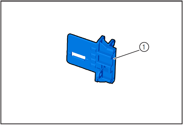
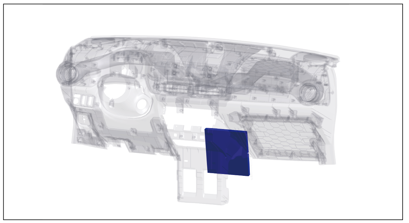
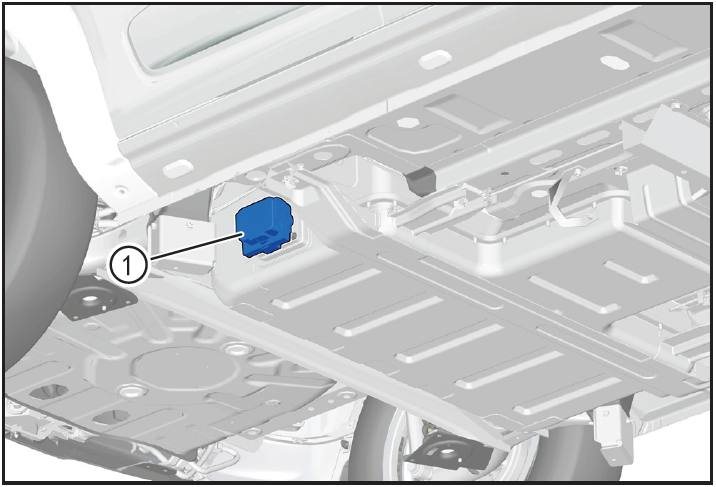
Disassembly and Installation of Speed Module
1-Part position
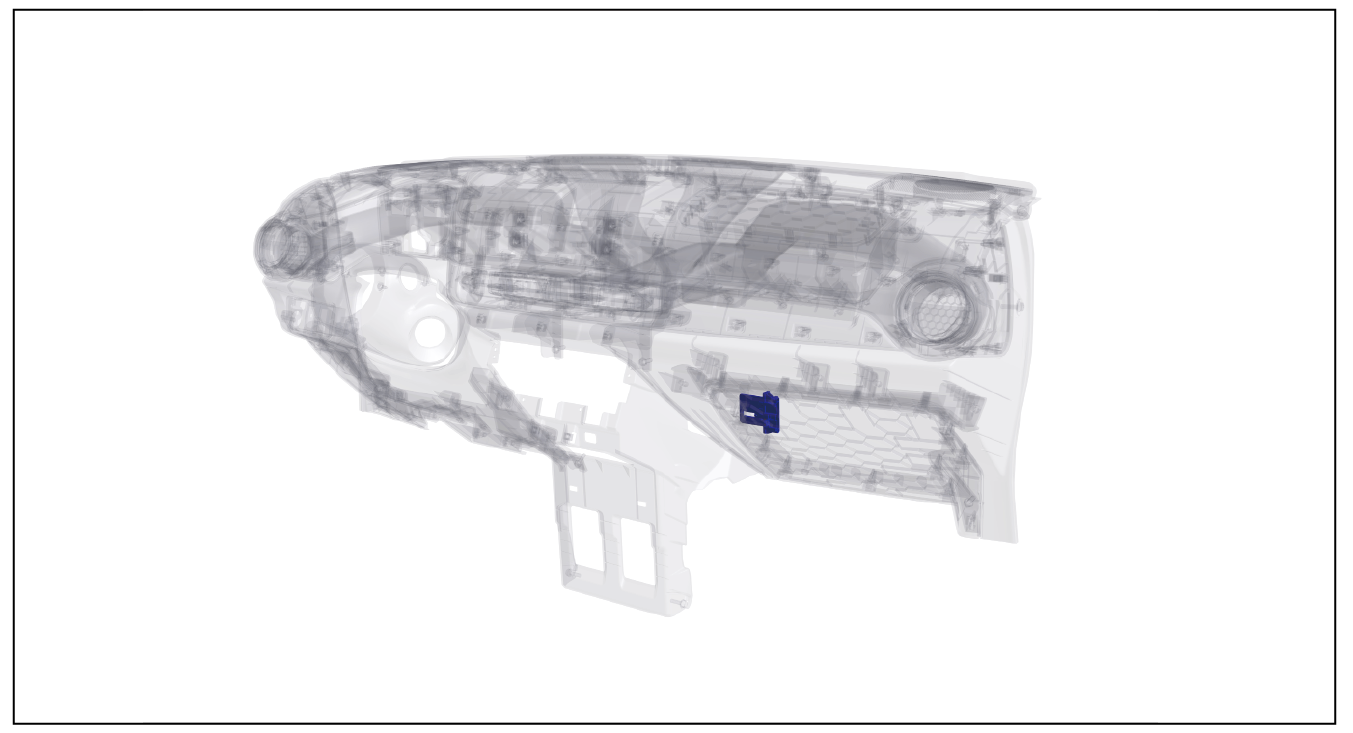
The speed control module is installed on the inner side of the instrument panel and below the blower
2-Component structure diagram
3-Protection
Place protective pads at the following positions:
- Front fender;
- Front bumper;
- Driver's seat;
- Carpet (driver's side);
- Steering wheel.
警告!
- Carefully read and master the maintenance precautions in this chapter (refer to "Precautions" in this chapter) before proceeding to the next operation.
4-Vehicle low voltage circuit locking
- Refer to "Vehicle Low Voltage Circuit Locking and Unlocking" in the chapter "Power Battery System" for the following operation
Vehicle ECU dormancy

- Register electric vehicle information, check instrument indicator light and sleep ECU.
Disconnect the positive and negative cables of the battery
- Disconnect the negative cable ① and positive cable ② of the battery.
注意!
- After disconnecting the negative cable of the battery, pay attention to avoid short connection between positive and negative electrodes.
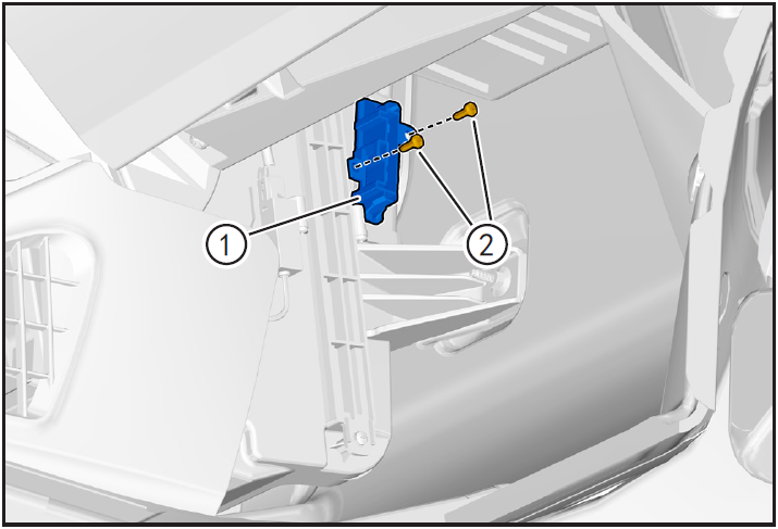
5-Remove
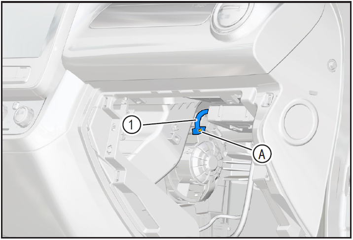
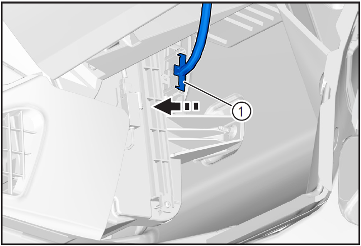
Removing speed control module
- Press and hold the adjustable-speed module connector locking clip (A) and disengage the adjustable-speed module connector ① in the direction of the arrow.
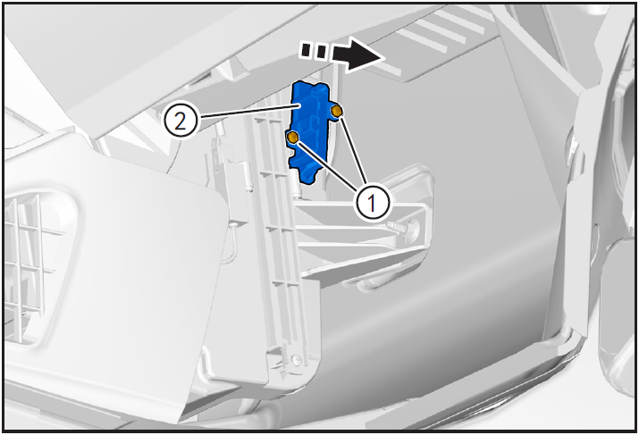
- Remove the two fixing screws ① of the speed regulating module by using the cross lift, and lower and take the speed regulating module ② along the arrow.
6-Check
- Check whether the pins of block ① of speed regulation mold are corroded or missing. If so, please replace them with new ones for installation.
7-Installation
Installing speed control module
- Place the speed control module ① to the installation position.
- Install 2 fixing screws ② of speed control module with cross lift.
- Install the speed module connector ① in the direction of the arrow until you hear the "click" sound and install it in place.
8-Vehicle low voltage circuit unlock
- Refer to "Vehicle Low Voltage Circuit Locking and Unlocking" in the chapter "Power Battery System" for the following operation
Install battery positive and negative cables

- Install battery negative cable ① and positive cable ②.
9-Clear fault code, check
- After installation, turn the ignition switch to "ON", connect the diagnostic instrument, and clear the fault code.
- After installation, check and confirm that the blower function is normal.
- Remove safety warning fences and warning signs.
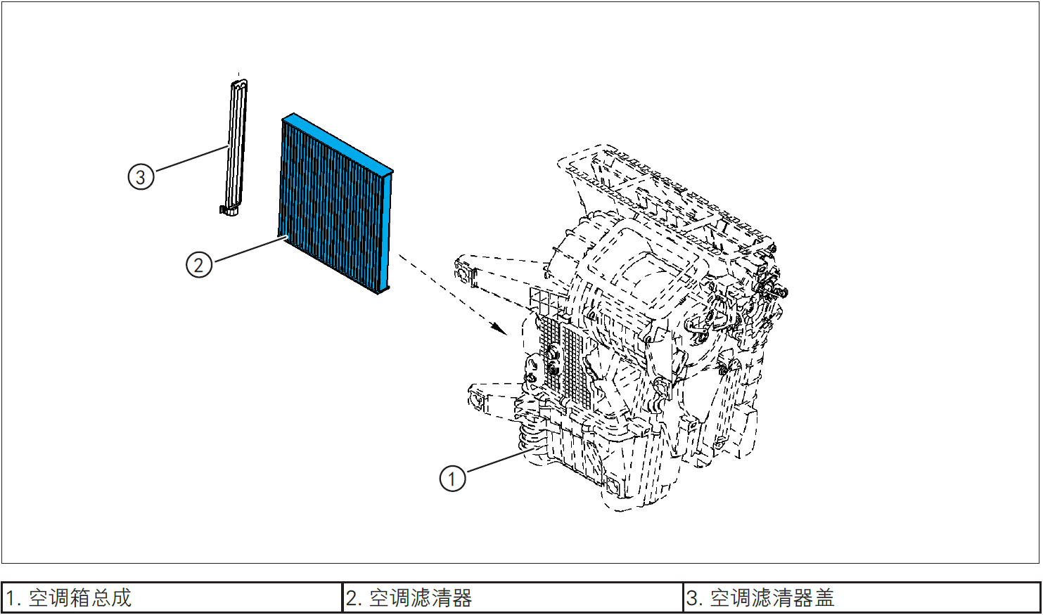
Air conditioning filter
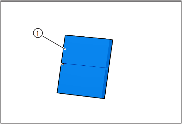
Disassembly and Installation of Filter Element of Air Conditioning Filter
1-Part position
The air conditioner filter is installed inside the air conditioner box and beside the glove box
2-Component structure diagram
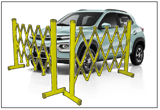
3-Protection

Place protective pads at the following positions:
- Front fender;
- Front bumper;
- Driver's seat;
- Carpet (driver's side);
- Steering wheel.
警告!
- Carefully read and master the maintenance precautions in this chapter (refer to "Precautions" in this chapter) before proceeding to the next operation.
4-Vehicle low voltage circuit locking
- Refer to "Vehicle Low Voltage Circuit Locking and Unlocking" in the chapter "Power Battery System" for the following operation
Vehicle ECU dormancy
- Register electric vehicle information, check instrument indicator light and sleep ECU.
Disconnect the positive and negative cables of the battery
- Disconnect the negative cable ① and positive cable ② of the battery.
注意!
- After disconnecting the negative cable of the battery, pay attention to avoid short connection between positive and negative electrodes.
5-Remove
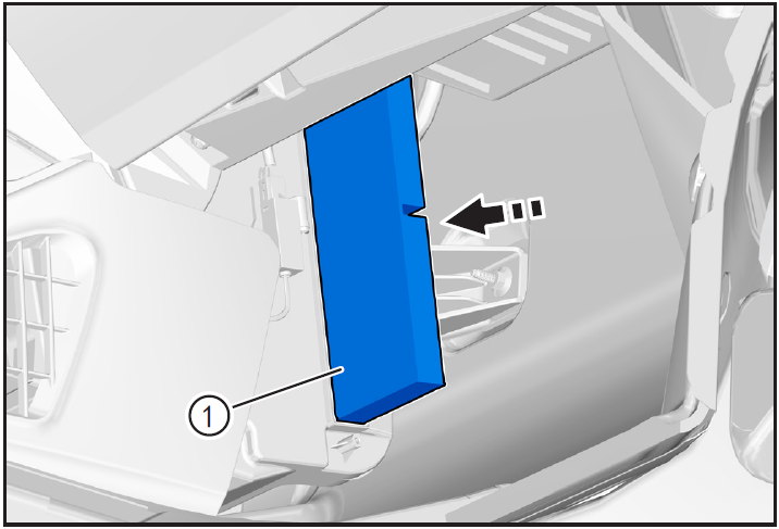
Removing air conditioning filter element
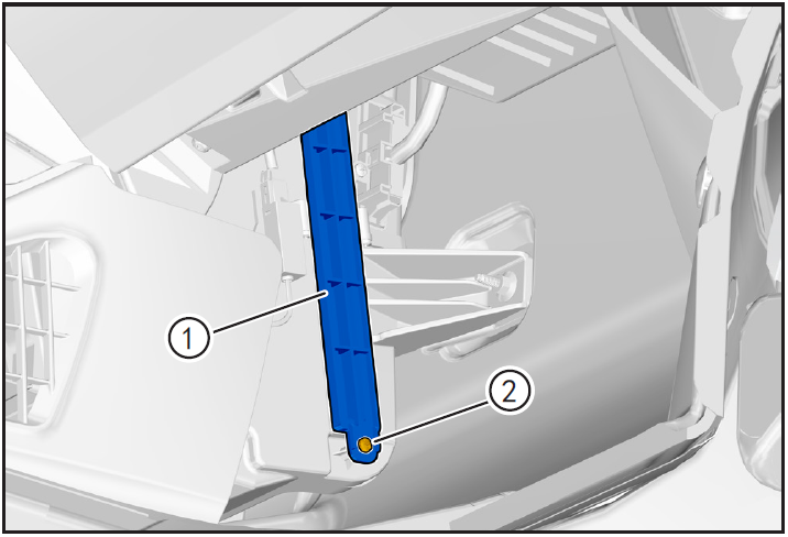
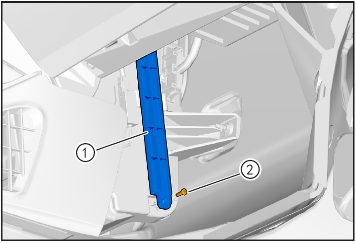
- Remove the fixing screw ② of the air-conditioning filter cover ① by using the cross lift, and remove the air-conditioning filter cover.
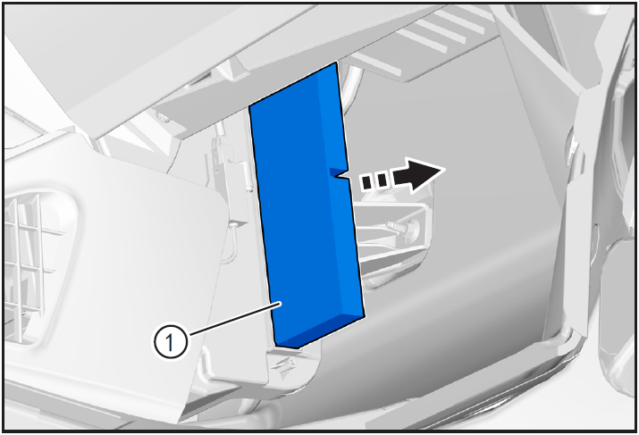
- Take out the air conditioner filter element ① in the direction of arrow.
6-Clean
- Check the status of air-conditioning filter element ①, and clean or replace the air filter element in time according to the recommended interval.
- Blow in with compressed air from the back of air filter 7-mounting cleaner filter element (opposite to the inlet air) until nothing is blown out.
7-Installation
Installing air conditioning filter element
- Install air conditioning filter element ① in place in the direction of arrow.
注意!
- Pay attention to the installation direction of air conditioning filter element.
- Install the air conditioning filter cover ① to ensure that it is installed in place.
- Install the fixing screws ② using the cross lift.
8-Vehicle low voltage circuit unlock
- Refer to "Vehicle Low Voltage Circuit Locking and Unlocking" in the chapter "Power Battery System" for the following operation
Install battery positive and negative cables
- Install battery negative cable ① and positive cable ②.
9-Clear fault code, check
- After installation, turn the ignition switch to "ON", connect the diagnostic instrument, and clear the fault code.
- After installation, check and confirm that the blower function is normal.
- Remove safety warning fences and warning signs.
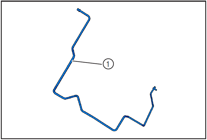
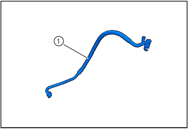
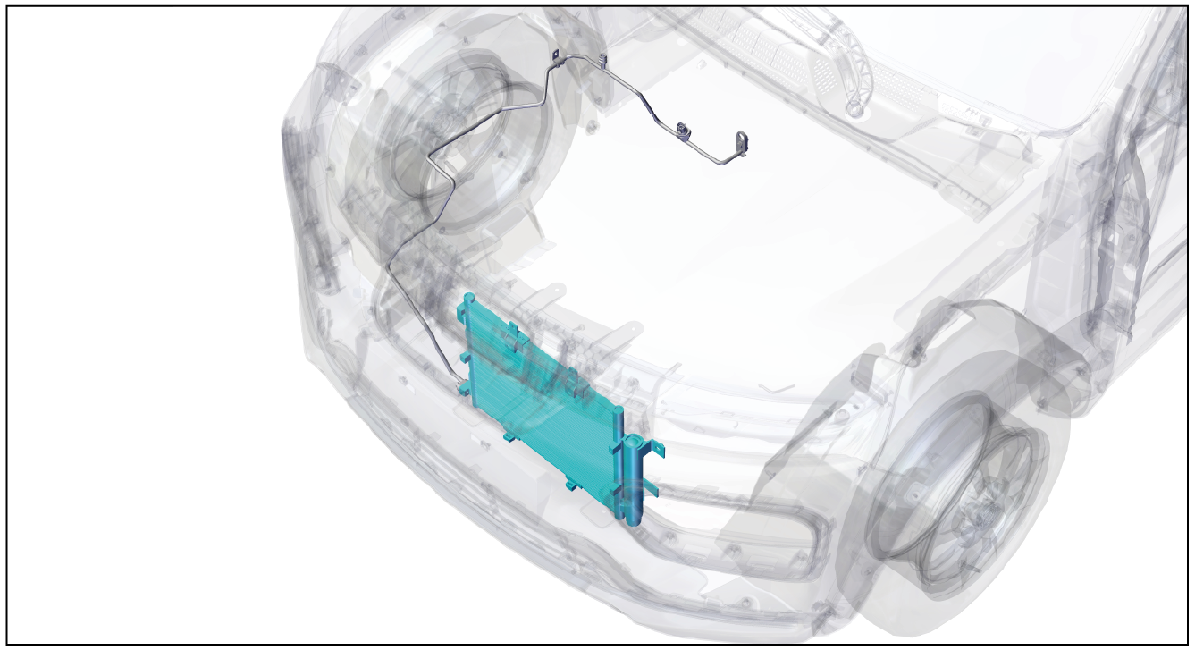
Air conditioning pipeline assembly
Removal and installation of high pressure pipeline (condenser to expansion valve)
1-Part position
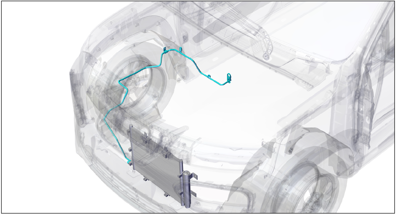
The high-pressure pipeline is installed in the powertrain cabin and connects the condenser with the expansion valve
2-Component structure diagram
3-Protection
Place protective pads at the following positions:
- Front fender;
- Front bumper;
- Driver's seat;
- Carpet (driver's side);
- Steering wheel.
警告!
- Carefully read and master the maintenance precautions in this chapter (refer to "Precautions" in this chapter) before proceeding to the next operation.
4-Vehicle low voltage circuit locking
- Refer to "Vehicle Low Voltage Circuit Locking and Unlocking" in the chapter "Power Battery System" for the following operation
Vehicle ECU dormancy

- Register electric vehicle information, check instrument indicator light and sleep ECU.
Disconnect the positive and negative cables of the battery
- Disconnect the negative cable ① and positive cable ② of the battery.
注意!
- After disconnecting the negative cable of the battery, pay attention to avoid short connection between positive and negative electrodes.
5-Remove
Refrigerant recovery
- Recovery of refrigerant. (Refer to "Refrigerant Recovery/Vacuumizing/Filling/Leak Checking" in this section)
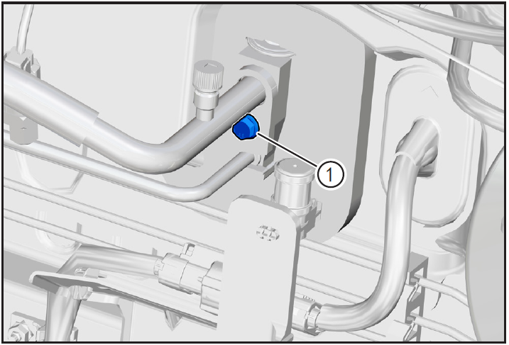
Removing air conditioning pressure switch

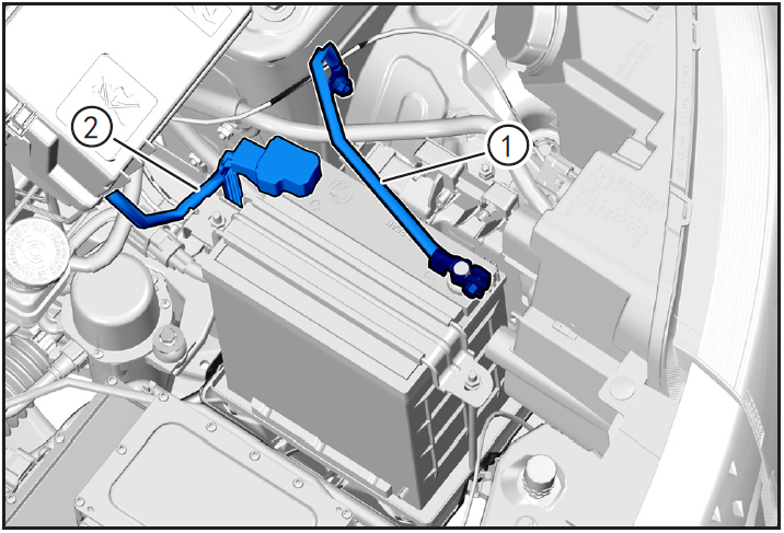
- Remove air conditioning pressure switch ①. (Refer to "Removal and Installation of Air Conditioning Pressure Switch" in this section.)
注意!
- There is still a small amount of refrigerant in the high-pressure pipe of the air conditioner. Protect it before disconnecting the high-pressure switch of the air conditioner. After disconnecting, wipe the spilled refrigerant clean.
- Because of the strong hygroscopicity of air-conditioning refrigerant oil, after disassembling the pipeline, block the pipeline joint with clean cloth.
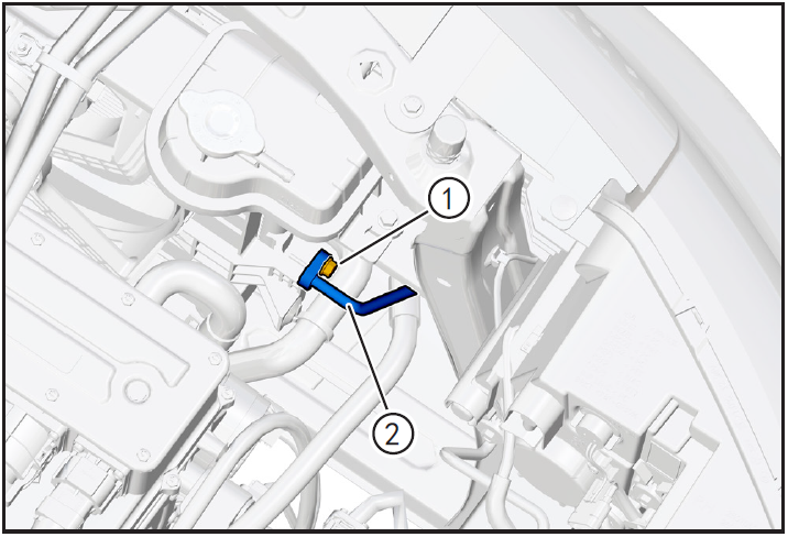
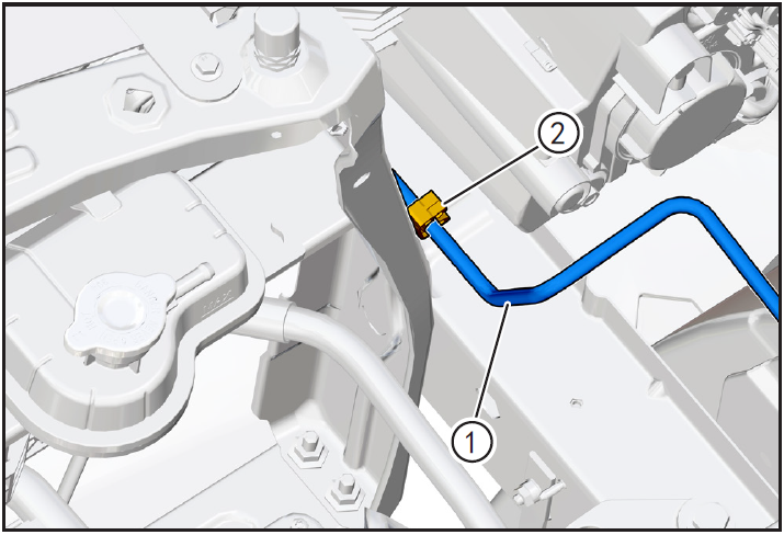
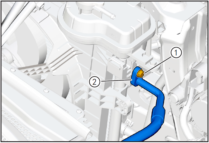
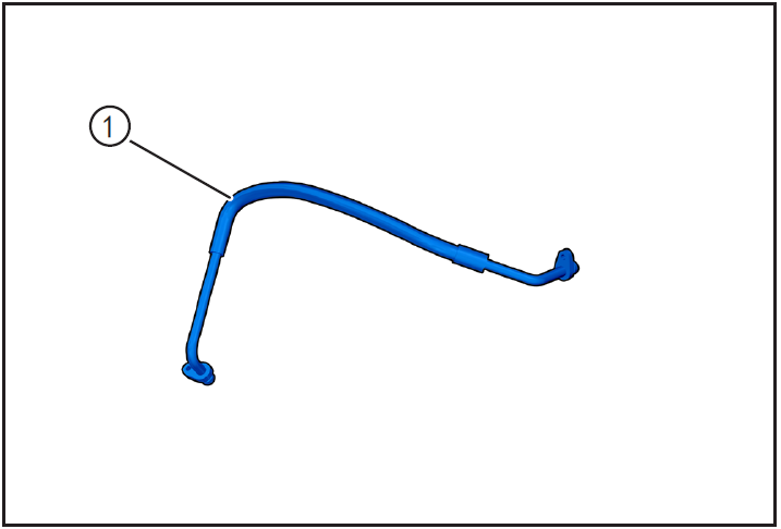
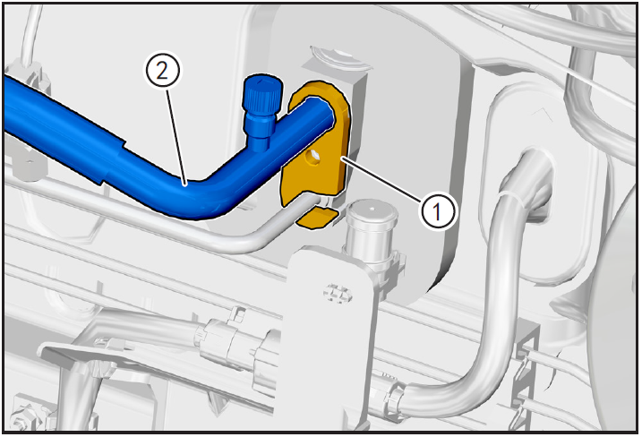
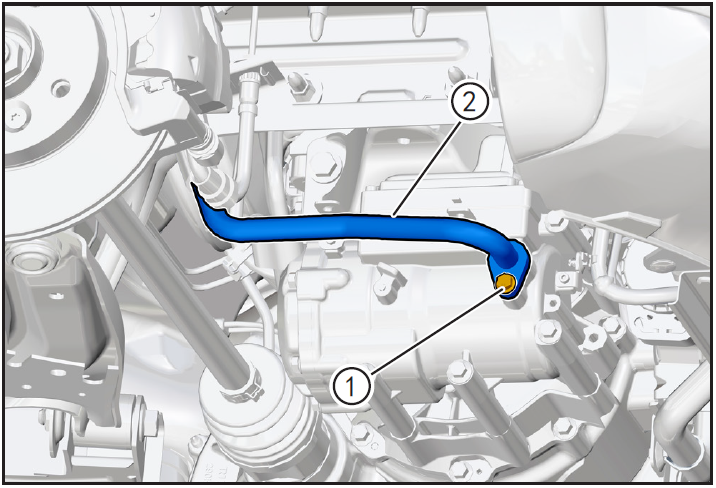
Removing air conditioning high pressure line (condenser to expansion valve)
- Remove the air conditioning high pressure line and expansion valve connecting bolt ① (M6 × 20) using a 10mm sleeve.
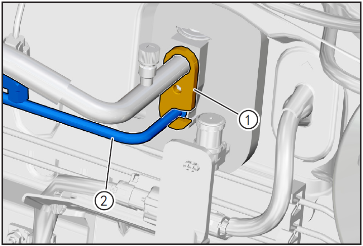
- Adjust the pressure sheet ① of air-conditioning high-pressure pipeline, and carefully shake the end of air-conditioning high-pressure pipeline ② (condenser to expansion valve) to make it separate from the fixed end of expansion valve outward.
注意!
- After disconnecting the end of the high-pressure pipeline of the air conditioner, wrap both ends of the pipeline joint with clean cloth sheets.
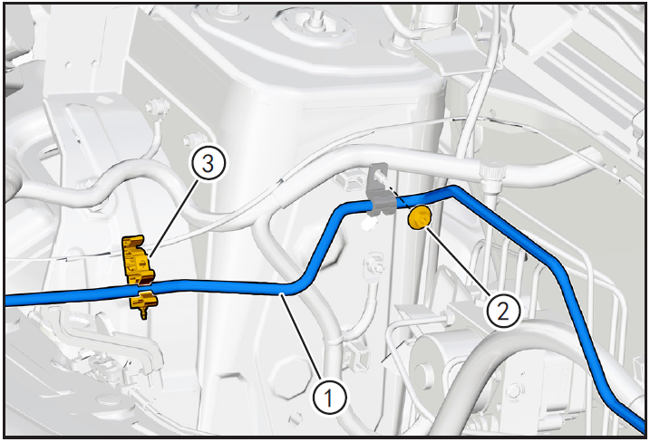
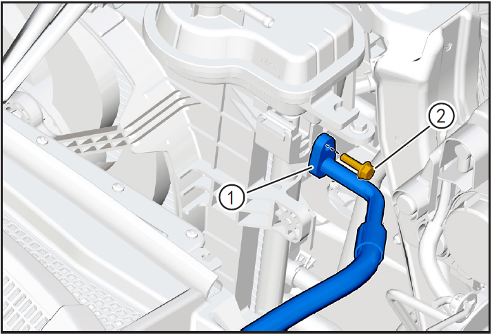
- Use 10mm sleeve to remove the fastening nut of the fixing pipe clamp of air-conditioning high-pressure pipeline ①.
- Remove the air-conditioning high-pressure pipeline ① from the fixed pipe clamp ③.

- Remove the air-conditioning high-pressure line ① from the fixed pipe clamp ②.
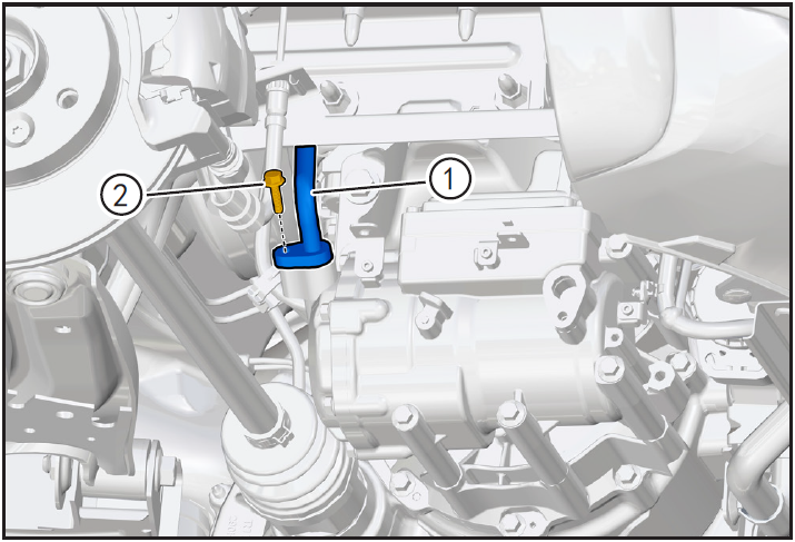
- Remove the fixing bolt ① of air-conditioning high-pressure pipeline (condenser end) with 10mm sleeve, disengage air-conditioning high-pressure pipeline, adjust air-conditioning high-pressure pipeline ② (condenser to expansion valve) and take it out.
注意!
- After disconnecting the end of the air-conditioning pipeline, wrap both ends of the pipeline joint with clean cloth sheets.
6-Check
- Check whether the joint of air-conditioning high-pressure pipeline ① (condenser to expansion valve) is damaged or corroded, and whether the joint of nozzle is deformed. If so, replace the new air-conditioning high-pressure pipeline for installation.
7-Installation
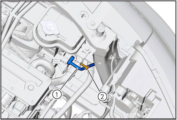
Install air conditioning high pressure line (condenser to expansion valve)

- Place the air-conditioning high-pressure line ① (condenser to expansion valve) to the initial installation position to ensure that the high-pressure line is installed correctly.
- Align the fixing pipe clamp of air-conditioning high-pressure pipeline with the stud and install the fixing nut ②, and tighten it with a 10mm sleeve with a tightening torque of 8N m.
- Align the air conditioner high-pressure pipeline with the fixed pipe clamp ③ and install it in place.
- Align the air conditioner high-pressure pipeline ① with the fixed pipe clamp ② and install it in place.
- Replace the O-ring of new air-conditioning high-pressure pipeline (condenser end) for installation.
- Before installation, apply a little refrigerant oil to the O-ring of the pipe joint.
- Install the air-conditioning high-pressure pipeline ① aligned with the condenser end in place, bring in the fixing bolt ② (M6 × 20), and tighten it with a 10mm sleeve with a tightening torque of 8N m.
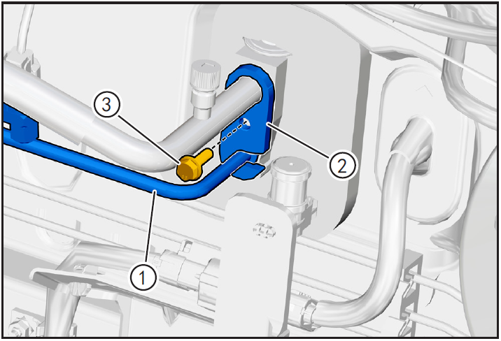
- Replace the O-ring of new air-conditioning high-pressure pipeline (expansion valve end) for installation.
- Before installation, apply a little refrigerant oil to the O-ring of the pipe joint.
- Align the air-conditioning high-pressure pipeline ① with the end of the expansion valve and install it in place, and adjust the tabletting of the air-conditioning high-pressure pipeline ②.
- Bring in the fixing bolt ③ (M6 × 20) and tighten it with a 10mm sleeve with a tightening torque of 8N m.
Installing air conditioning pressure switch
- Install air conditioning pressure switch ①. (Refer to "Removal and Installation of Air Conditioning Pressure Switch" in this section.)
8-Vehicle low voltage circuit unlock
- Refer to "Vehicle Low Voltage Circuit Locking and Unlocking" in the chapter "Power Battery System" for the following operation
Install battery positive and negative cables

- Install battery negative cable ① and positive cable ②.
9-Refrigerant filling
Refrigerant filling

- Fill refrigerant and carry out refrigerant leak detection operation. (Refer to "Refrigerant Recovery/Vacuumizing/Filling/Leak Checking" in this section)
10-Clear fault code, check
- After installation, turn the ignition switch to "ON", connect the diagnostic instrument, and clear the fault code.
- Turn on the ignition switch, operate the air conditioning control panel, check and confirm that all functions of the air conditioning system work normally.
- Remove safety warning fences and warning signs.
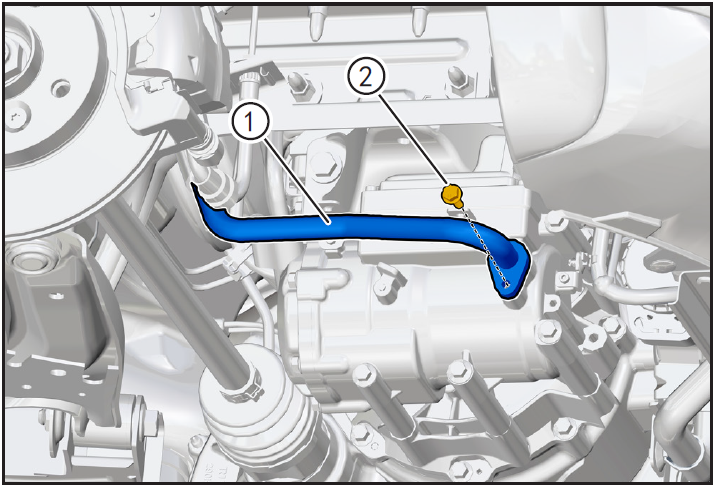
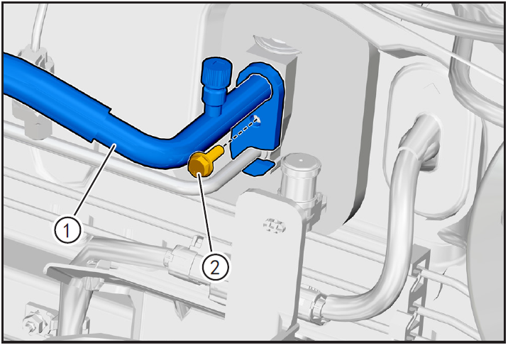
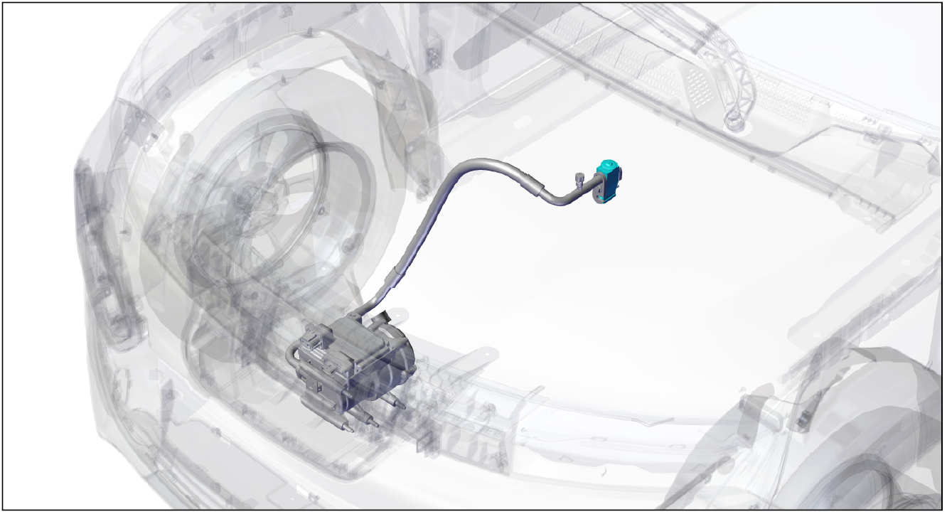
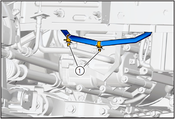
Removal and installation of high pressure pipeline (compressor to condenser)
1-Part position
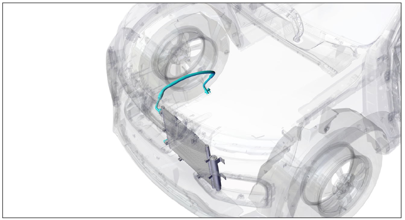
The high-pressure pipeline is installed in the powertrain cabin and connects the compressor and condenser
2-Component structure diagram
3-Protection

Place protective pads at the following positions:
- Front fender;
- Front bumper;
- Driver's seat;
- Carpet (driver's side);
- Steering wheel.
警告!
- Carefully read and master the maintenance precautions in this chapter (refer to "Precautions" in this chapter) before proceeding to the next operation.
4-Vehicle low voltage circuit locking
- Refer to "Vehicle Low Voltage Circuit Locking and Unlocking" in the chapter "Power Battery System" for the following operation
Vehicle ECU dormancy

- Register electric vehicle information, check instrument indicator light and sleep ECU.
Disconnect the positive and negative cables of the battery
- Disconnect the negative cable ① and positive cable ② of the battery.
注意!
- After disconnecting the negative cable of the battery, pay attention to avoid short connection between positive and negative electrodes.
5-Remove
Refrigerant recovery

- Recovery of refrigerant. (Refer to "Refrigerant Recovery/Vacuumizing/Filling/Leak Checking" in this section)
Removing high pressure line (compressor to condenser)
- Remove the high pressure line (compressor end) fixing bolt ① with 10mm sleeve and disconnect the high pressure line ②.
注意!
- There is still a small amount of refrigerant in the high-pressure pipe of the air conditioner. Protect it before disconnecting the fixed end of the high-pressure pipe of the air conditioner. After disconnecting, wipe the spilled refrigerant clean.
- Because of the strong hygroscopicity of air-conditioning refrigerant oil, after disassembling the pipeline, block the pipeline joint with clean cloth.
- Remove the fixing bolt ① of high-pressure pipeline (condenser end) with 10mm sleeve, disconnect the high-pressure pipeline ②, and remove the compressor of high-pressure pipeline ② to the condenser.
注意!
- After disconnecting the end of the air-conditioning pipeline, wrap both ends of the pipeline joint with clean cloth sheets.
6-Check
- Check whether the joint of air-conditioning high-pressure pipeline ① (compressor to condenser) is damaged or corroded, and whether the joint of nozzle is deformed. If so, replace the new air-conditioning high-pressure pipeline for installation.
7-Installation
Install high pressure line (compressor to condenser)
- Replace the O-ring at the end of high pressure pipeline (condenser) for installation.
- Before installation, apply a little refrigerant oil to the O-ring of the pipe joint.
- Install the air-conditioning high-pressure pipeline ① aligned with the condenser security end in place, bring in the fixing bolt ② (M6 × 20), and tighten it with a 10mm sleeve with a tightening torque of 8N m.
- Replace the O-ring at the air conditioning pipeline (compressor) end for installation.
- Before installation, apply a little refrigerant oil to the O-ring of the pipe joint.
- Align the air conditioner high-pressure pipeline ① with the compressor installation end and install it in place, bring in the fixing bolt ② (M6 × 20), and tighten it with a 10mm sleeve with a tightening torque of 8N m.
8-Vehicle low voltage circuit unlock
- Refer to "Vehicle Low Voltage Circuit Locking and Unlocking" in the chapter "Power Battery System" for the following operation
Install battery positive and negative cables

Install battery negative cable ① and positive cable ②.
9-Refrigerant filling
Refrigerant filling
- Fill refrigerant and carry out refrigerant leak detection operation. (Refer to "Refrigerant Recovery/Vacuumizing/Filling/Leak Checking" in this section)
10-Clear fault code, check
- After installation, turn the ignition switch to "ON", connect the diagnostic instrument, and clear the fault code.
- Turn on the ignition switch, operate the air conditioning control panel, check and confirm that all functions of the air conditioning system work normally.
- Remove safety warning fences and warning signs.
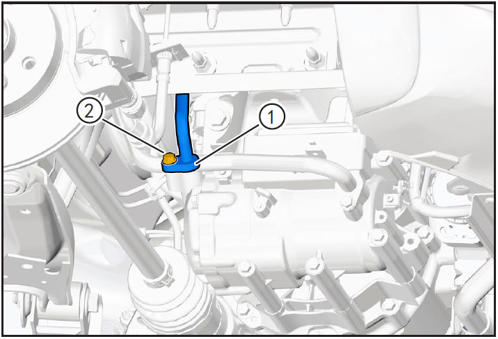
Removal and installation of low pressure pipeline (expansion valve to compressor)
1-Part position
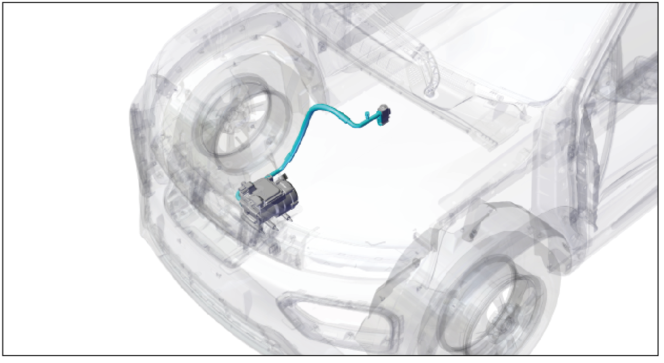
The low pressure pipeline is installed in the powertrain cabin and connects the expansion valve with the compressor
2-Component structure diagram
3-Protection
Place protective pads at the following positions:
- Front fender;
- Front bumper;
- Driver's seat;
- Carpet (driver's side);
- Steering wheel.
警告!
- Carefully read and master the maintenance precautions in this chapter (refer to "Precautions" in this chapter) before proceeding to the next operation.
4-Vehicle low voltage circuit locking
- Refer to "Vehicle Low Voltage Circuit Locking and Unlocking" in the chapter "Power Battery System" for the following operation
Vehicle ECU dormancy
- Register electric vehicle information, check instrument indicator light and sleep ECU.
Disconnect the positive and negative cables of the battery
- Disconnect the negative cable ① and positive cable ② of the battery.
注意!
- After disconnecting the negative cable of the battery, pay attention to avoid short connection between positive and negative electrodes.
5-Remove
Refrigerant recovery

- Recovery of refrigerant. (Refer to "Refrigerant Recovery/Vacuumizing/Filling/Leak Checking" in this section)
Remove air conditioning low pressure line (expansion valve to compressor)
- Remove air conditioning line and expansion valve connecting bolt ① (M6 × 20) using 10mm sleeve.
- Adjust the air-conditioning pressure line pressure sheet ①, carefully shake the air-conditioning low-pressure line ② (expansion valve to compressor) end, so that it is separated from the expansion valve fixed end outward.
注意!
- There is still a small amount of refrigerant in the air-conditioning pipeline. Protect it before disassembling the air-conditioning pipeline. After disassembling, wipe the spilled refrigerant clean.
- Because of the strong hygroscopicity of air-conditioning refrigerant oil, after removing the air-conditioning pressure switch, plug the joint with a clean cloth sheet.
- Remove the compressor low-pressure line fixing bolt ① with a 10mm sleeve, and carefully shake the end of the air-conditioning low-pressure line ② (expansion valve to compressor) to disconnect it from the compressor fixing end outward.
注意!
- After disconnecting the end of the low-pressure pipeline of the air conditioner, wrap both ends of the pipeline joint with clean cloth sheets.
6-Check
- Check whether the joint of air-conditioning low-pressure pipeline ① (expansion valve to compressor) is damaged or corroded, and whether the joint of nozzle is deformed. If so, replace the new air-conditioning low-pressure pipeline for installation.
7-Installation
Install air conditioning low pressure line (expansion valve to compressor)
- Replace the O-ring at the end of the low pressure pipeline (compressor) for installation.
- Before installation, apply a little refrigerant oil to the O-ring of the pipe joint.
- Install the air conditioner low-pressure pipeline ① aligned with the compressor safety end in place, bring in the fixing bolt ② (M6 × 20), and tighten it with a 10mm sleeve with a tightening torque of 8N m.
- Replace the O-ring at the end of the air conditioning pipeline (expansion valve) for installation.
- Before installation, apply a little refrigerant oil to the O-ring of the pipe joint.
- Install the air conditioner low-pressure pipeline ① aligned with the installation end of the expansion valve in place, bring in the fixing bolt ② (M6 × 20), and tighten it with a 10mm sleeve with a tightening torque of 8N m.
8-Vehicle low voltage circuit unlock
- Refer to "Vehicle Low Voltage Circuit Locking and Unlocking" in the chapter "Power Battery System" for the following operation
Install battery positive and negative cables

- Install battery negative cable ① and positive cable ②.
9-Refrigerant filling
Refrigerant filling

- Fill refrigerant and carry out refrigerant leak detection operation. (Refer to "Refrigerant Recovery/Vacuumizing/Filling/Leak Checking" in this section)
10-Clear fault code, check
- After installation, turn the ignition switch to "ON", connect the diagnostic instrument, and clear the fault code.
- Turn on the ignition switch, operate the air conditioning control panel, check and confirm that all functions of the air conditioning system work normally.
- Remove safety warning fences and warning signs.
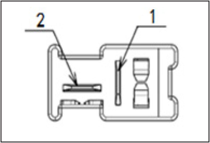
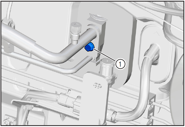
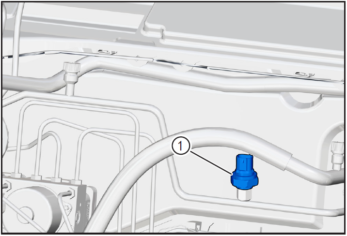
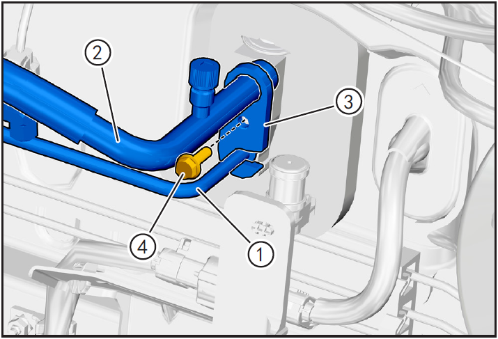
Air conditioning pressure switch
Disassembly and Installation of Air Conditioning Pressure Switch
1-Part position
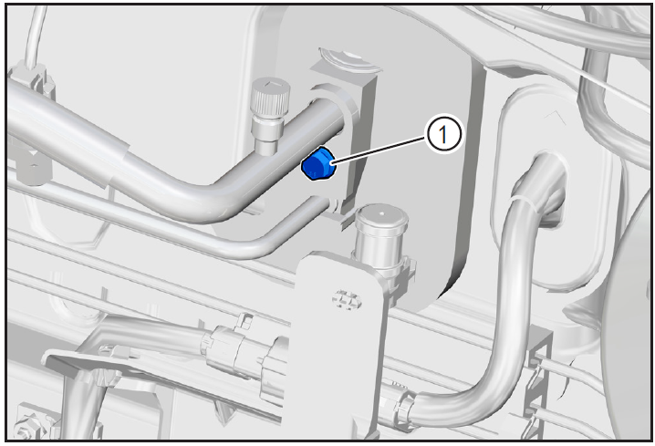
The air conditioning pressure switch is installed on the air conditioning pipe from the condenser to the expansion valve
2-Component structure diagram
3-Protection

Place protective pads at the following positions:
- Front fender;
- Front bumper;
- Driver's seat;
- Carpet (driver's side);
- Steering wheel.
警告!
- Carefully read and master the maintenance precautions in this chapter (refer to "Precautions" in this chapter) before proceeding to the next operation.
4-Vehicle low voltage circuit locking
- Refer to "Vehicle Low Voltage Circuit Locking and Unlocking" in the chapter "Power Battery System" for the following operation
Vehicle ECU dormancy

- Register electric vehicle information, check instrument indicator light and sleep ECU.
Disconnect the positive and negative cables of the battery
- Disconnect the negative cable ① and positive cable ② of the battery.
注意!
- After disconnecting the negative cable of the battery, pay attention to avoid short connection between positive and negative electrodes.
5-Remove
Refrigerant recovery
- Recovery of refrigerant. (Refer to "Refrigerant Recovery/Vacuumizing/Filling/Leak Checking" in this section)
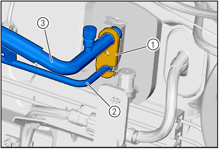
Disengage air conditioning pressure switch connector
- Press and hold the air conditioner pressure switch connector locking clip (A) to disengage the air conditioner pressure connector ①.
Removing air conditioning pressure switch

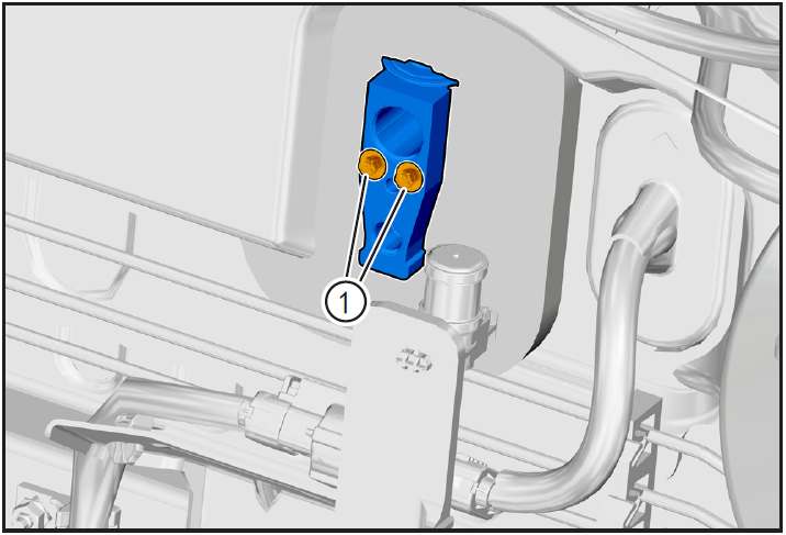
- Secure pressure sensor block ① with a 17mm wrench and remove air conditioning pressure switch ② with a 24mm open-ended wrench.
注意!
- There is still a small amount of refrigerant in the high-pressure pipe of the air conditioner. Protect it before disconnecting the fixed end of the high-pressure pipe of the air conditioner. After disconnecting, wipe the spilled refrigerant clean.
- Because of the strong hygroscopicity of air-conditioning refrigerant oil, after disassembling the pipeline, block the pipeline joint with clean cloth.
6-Installation
Installing air conditioning pressure switch
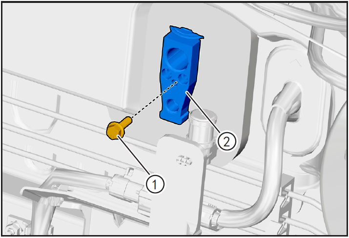
- Replace with a new O-ring ① for installation.
- Before installation, apply a little refrigerant oil to the O-ring of air conditioner pressure switch.

- Screw the air conditioner pressure switch ① into the mounting hole slowly to confirm that the air conditioner pressure switch is installed correctly.
- Secure pressure sensor block ② with a 17mm wrench and tighten air conditioning pressure switch ① with a 24mm open-ended wrench.
Installing air conditioning pressure switch connector
- Install the air-conditioning pressure switch connector ① until you hear the "click" sound and install it in place.
7-Vehicle low voltage circuit unlock
- Refer to "Vehicle Low Voltage Circuit Locking and Unlocking" in the chapter "Power Battery System" for the following operation
Install battery positive and negative cables

- Install battery negative cable ① and positive cable ②.
注意!
- After disconnecting the negative cable of the battery, pay attention to avoid short connection between positive and negative electrodes.
5-Remove
Refrigerant recovery
- Recovery of refrigerant. (Refer to "Refrigerant Recovery/Vacuumizing/Filling/Leak Checking" in this section)
Disengage air conditioning pressure switch connector
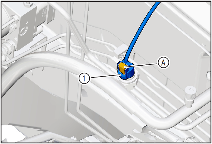
- Press and hold the air conditioner pressure switch connector locking clip (A) to disengage the air conditioner pressure connector ①.
Removing air conditioning pressure switch
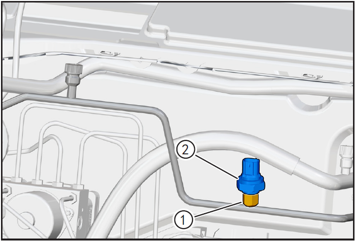
- Secure pressure sensor block ① with a 17mm wrench and remove air conditioning pressure switch ② with a 24mm open-ended wrench.
注意!
- There is still a small amount of refrigerant in the high-pressure pipe of the air conditioner. Protect it before disconnecting the fixed end of the high-pressure pipe of the air conditioner. After disconnecting, wipe the spilled refrigerant clean.
- Because of the strong hygroscopicity of air-conditioning refrigerant oil, after disassembling the pipeline, block the pipeline joint with clean cloth.
6-Installation
Installing air conditioning pressure switch

- Replace with a new O-ring ① for installation.
- Before installation, apply a little refrigerant oil to the O-ring of air conditioner pressure switch.
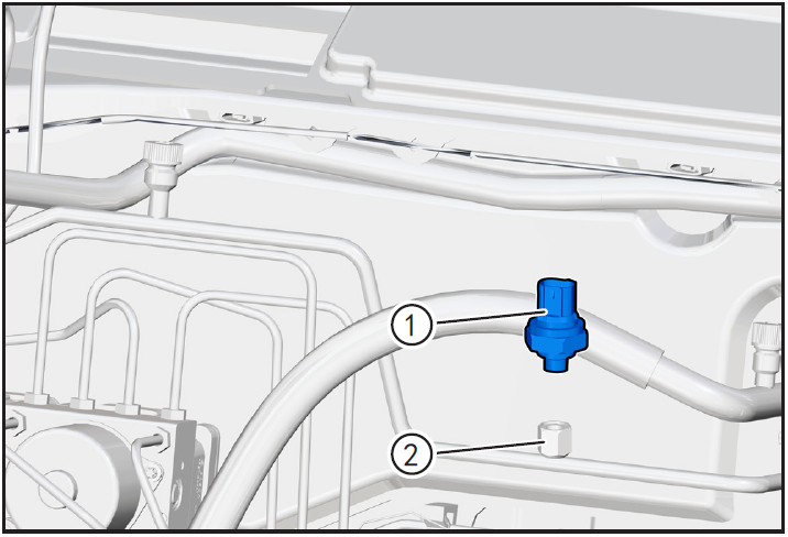
- Screw the air conditioner pressure switch ① into the mounting hole slowly to confirm that the air conditioner pressure switch is installed correctly.
- Secure the pressure sensor block ② using a 17mm mounting air-conditioning pressure switch connector wrench and tighten the air-conditioning pressure switch ① using a 24mm open-ended wrench.
Installing air conditioning pressure switch connector

- Install the air-conditioning pressure switch connector ① until you hear the "click" sound and install it in place.
7-Vehicle low voltage circuit unlock
- Refer to "Vehicle Low Voltage Circuit Locking and Unlocking" in the chapter "Power Battery System" for the following operation
Install battery positive and negative cables

- Install battery negative 8-refrigerant charging pole cable ① and positive pole cable ②.
8-Refrigerant filling
Refrigerant filling
- Fill refrigerant and carry out refrigerant leak detection operation. (Refer to "Refrigerant Recovery/Vacuumizing/Filling/Leak Checking" in this section)
9-Clear fault code, check
- After installation, turn the ignition switch to "ON", connect the diagnostic instrument, and clear the fault code.
- Turn on the ignition switch, operate the air conditioning control panel, check and confirm that all functions of the air conditioning system work normally.
- Remove safety warning fences and warning signs.
Air conditioning expansion valve
Disassembly and Installation of Air Conditioning Expansion Valve
1-Part position
The air-conditioning expansion valve is installed at the joint of the air-conditioning pipeline and the air-conditioning box assembly
2-Component structure diagram
3-Protection
Place protective pads at the following positions:
- Front fender;
- Front bumper;
- Driver's seat;
- Carpet (driver's side);
- Steering wheel.
警告!
- Carefully read and master the maintenance precautions in this chapter (refer to "Precautions" in this chapter) before proceeding to the next operation.
4-Remove
Refrigerant recovery
- Recovery of refrigerant. (Refer to "Refrigerant Recovery/Vacuumizing/Filling/Leak Checking" in this section)
Disconnect the air conditioning line
- Remove air conditioning line and expansion valve connecting bolt ① (M6 × 16) using 10mm sleeve.
- Adjust the air-conditioning pipeline tabletting ①, carefully shake the ends of air-conditioning high-pressure pipe ② and air-conditioning low-pressure pipe ③, and make them separate from the fixed end of expansion valve outward.
- Move the air conditioning line to the non-interference position.
注意!
- There is still a small amount of refrigerant in the high-pressure pipe of the air conditioner. Protect it before disconnecting the fixed end of the high-pressure pipe of the air conditioner. After disconnecting, wipe the spilled refrigerant clean.
- Because of the strong hygroscopicity of air-conditioning refrigerant oil, after disassembling the pipeline, block the pipeline joint with clean cloth.
Removing expansion valve
- Remove the expansion valve retaining bolt ① using 4mm inner hexagon.
- Screw the connecting bolt (M6 × 16) between the air conditioning pipeline and the expansion valve into 2/3 of the expansion valve, and shake left and right to disconnect the expansion valve (2) from the evaporator connecting pipe.
- Remove expansion valve ②.
注意!
- In order to prevent the internal parts of the system from being contaminated by damp and dust, remove any pipeline from the system, and install a plug or dust cover at the joint to prevent contamination.
6-Check
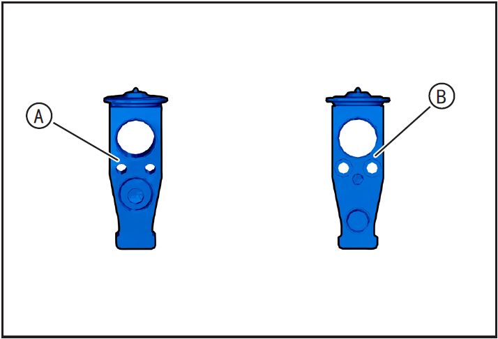
- (A) is the reverse side of the expansion valve, and (B) is the front side of the expansion valve.
- Before installing and using the expansion valve, check whether it is in good condition and whether the expansion valve is conductive. In order to ensure the normal operation of the expansion valve, it should be adiabatic and moisture-proof to avoid the interference of cold and hot airflow and objects.
7-Installation
Installing expansion valve
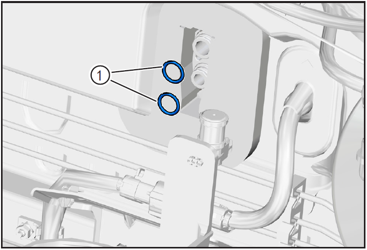
- Replace a new evaporator line O-ring ① for installation.
- Apply a little refrigerant oil to the O-ring of the new evaporator line.
- Clean the installation surface of expansion valve and its surroundings to ensure no dirt.
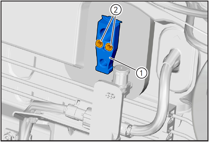
- Press the expansion valve ① into place at the evaporator line.
- Tighten the expansion valve fixing bolt ② using 4mm inner hexagon.
注意!
- Pay attention to the installation direction of expansion valve.
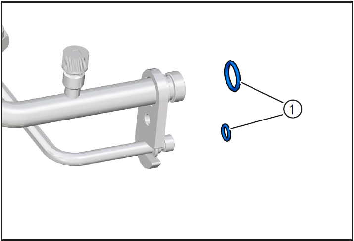
- Replace new O-ring ① for high and low pressure pipelines of air conditioner for installation.
- Align the air conditioner high pressure pipe ① with the expansion valve and install it in place.
- Align the air conditioner low pressure pipe ② with the expansion valve and install it in place.
- Adjust the air-conditioning pipeline tabletting ③, bring in the connecting bolt ④ (M6 × 16) between the air-conditioning pipeline and the expansion valve, and tighten it with a 10mm sleeve with a tightening torque of 8N m.
7-Vehicle low voltage circuit unlock
- Refer to "Vehicle Low Voltage Circuit Locking and Unlocking" in the chapter "Power Battery System" for the following operation
Install battery positive and negative cables
- Install battery negative cable ① and positive cable ②.
8-Refrigerant filling
Refrigerant filling
- Fill refrigerant and carry out refrigerant leak detection operation. (Refer to "Refrigerant Recovery/Vacuumizing/Filling/Leak Checking" in this section)
9-Clear fault code, check
- After installation, turn the ignition switch to "ON", connect the diagnostic instrument, and clear the fault code.
- Turn on the ignition switch, operate the air conditioning control panel, check and confirm that all functions of the air conditioning system work normally.
- Remove safety warning fences and warning signs.
Refrigerant filling

- Fill refrigeration 10-clear fault code, test agent and carry out refrigerant leak detection operation. (Refer to "Refrigerant Recovery/Vacuumizing/Filling/Leak Checking" in this section)
10-Clear fault code, test run
- After installation, turn the ignition switch to "ON", connect the diagnostic instrument, and clear the fault code.
- Check and confirm that the vehicle is running normally.
- Turn on the ignition switch, operate the air conditioning control panel, check and confirm that all functions of the air conditioning system work normally.
注意!
- Be sure to ensure that the 12V battery voltage is higher than 10V during operation.
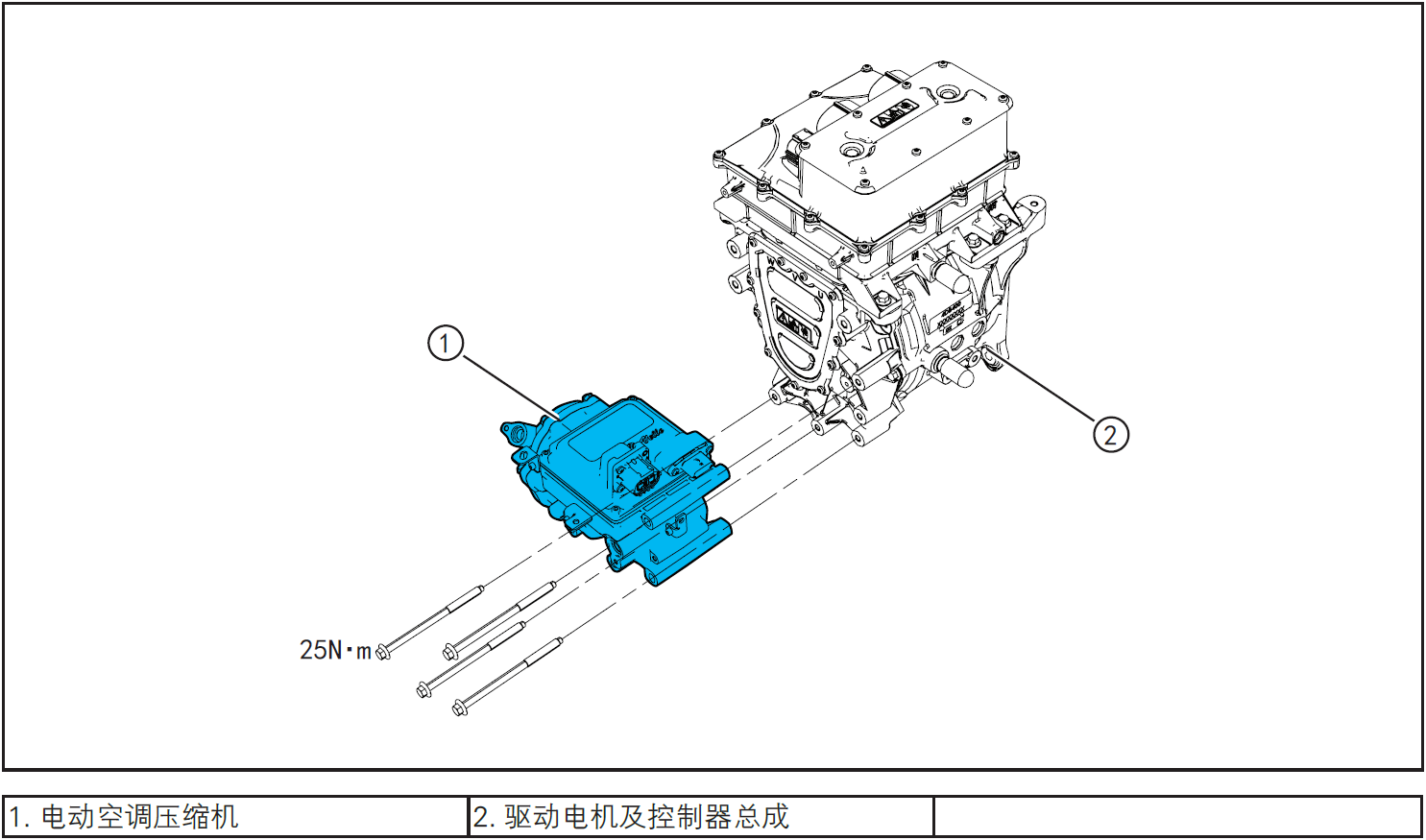
Electric compressor for air conditioning
Disassembly and Installation of Electric Compressor for Air Conditioning
1-Part position
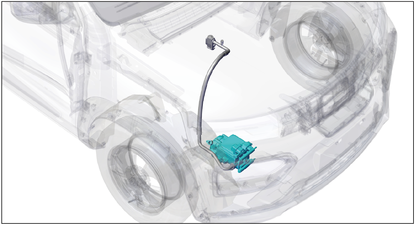
The air-conditioning compressor assembly is located at the right front of the powertrain cabin and is fixed on the powertrain through brackets and bolts
2-Component structure diagram
3-Protection

Place protective pads at the following positions:
- Front fender;
- Front bumper;
- Driver's seat;
- Carpet (driver's side);
- Steering wheel.
警告!
- Carefully read and master the maintenance precautions in this chapter (refer to "Precautions" in this chapter) before proceeding to the next operation.
4-Recommended Tools
- Internals Removal Tool (BBG1102) [1].
5-Vehicle high-pressure listing locking
- For the following operation of this step, refer to "Locking and Unlocking of Vehicle High Voltage Listing" in the chapter of "Power Battery System"
Vehicle ECU dormancy

- Register electric vehicle information, check instrument indicator light and sleep ECU.
Remove the service switch
- Remove service switch ①.
Disconnect the positive and negative cables of the battery

- Disconnect the negative cable ① and positive cable ② of the battery.
注意!
- After disconnecting the negative cable of the battery, cover the positive and negative electrodes with a clean and insulating protective cover to avoid short connection between the positive and negative electrodes.
Zero voltage test
- Use VAT test meter to measure the terminal. If the voltage is 0V, it shows that the high-voltage system is discharged and there is no high voltage;
- If the voltage is not 0V, do not carry out maintenance operation, otherwise high voltage electric shock may occur, wait for the voltage to be 0V before carrying out maintenance operation.
6-Remove
Refrigerant recovery
- Recovery of refrigerant. (Refer to "Refrigerant Recovery/Vacuumizing/Filling/Leak Checking" in this section)
Disassembly of high voltage cable of electric compressor
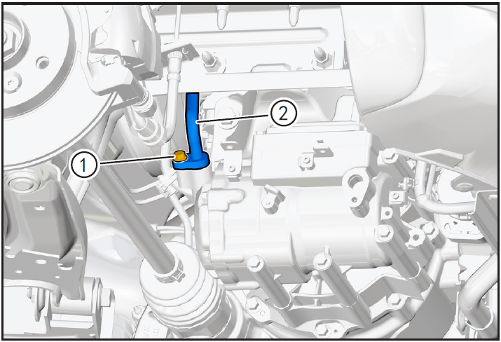
- Using the interior trim removal tool (BBG1102), detach the high voltage cable retaining card ① of the electric air conditioner compressor.
- Lower the vehicle to an appropriate height.
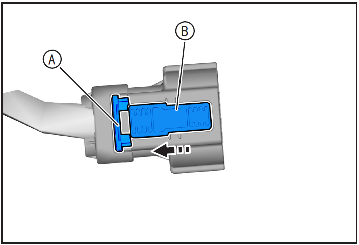
- Disengage the high-voltage cable connector locking clamp (A) of the electric air-conditioning compressor in the direction of arrow, press and hold the high-voltage cable connector locking clamp (B) of the electric air-conditioning compressor, and disengage the high-voltage cable connector ① of the electric air-conditioning compressor.
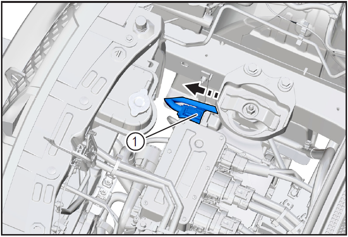
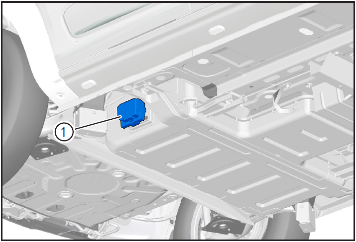
Removal of ground wire harness for electric air conditioning compressor
- Remove the electric air-conditioning compressor ground harness fixing bolt ① using the E8 sleeve and move the electric air-conditioning compressor ground harness ② to the non-interference position.
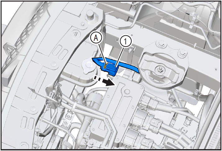
Disengage the low pressure pipeline of the electric air conditioner compressor
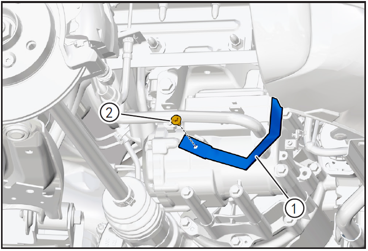
- Remove the low pressure line fixing bolt ① of the electric air conditioner compressor with a 10mm sleeve, and move the low pressure line ② of the electric air conditioner compressor to a non-interference position.
注意!
- There is still a small amount of refrigerant in the air-conditioning pipeline. Protect it before disassembling the air-conditioning pipeline. After disassembling, wipe the spilled refrigerant clean.
- Because of the strong hygroscopicity of air-conditioning refrigerant oil, after removing the air-conditioning pressure switch, plug the joint with a clean cloth sheet.
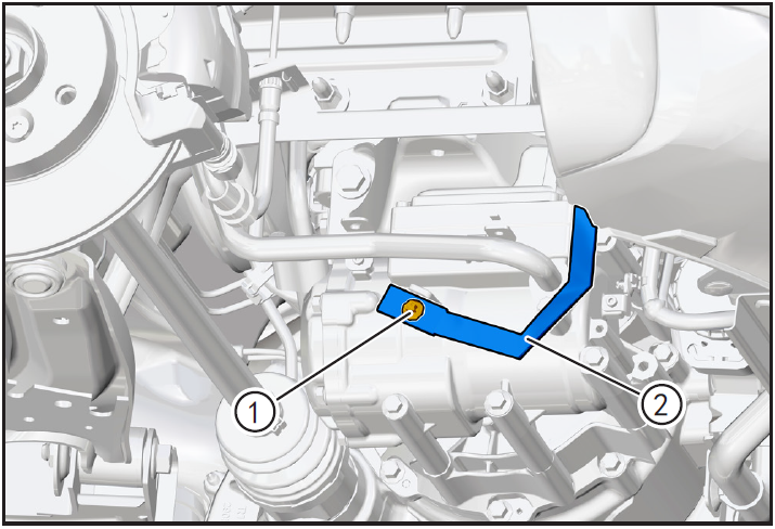
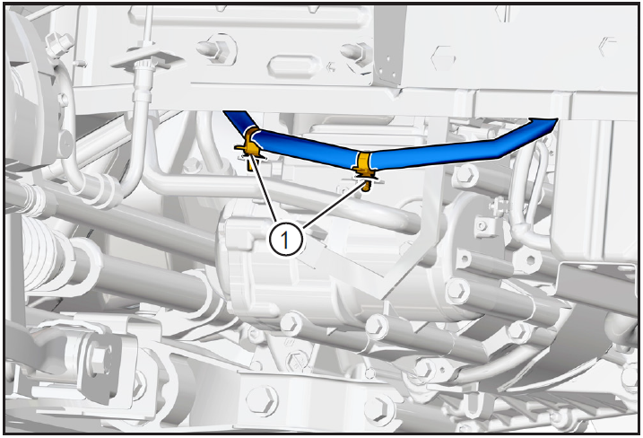
Disengage the high-pressure pipeline of the electric air-conditioning compressor
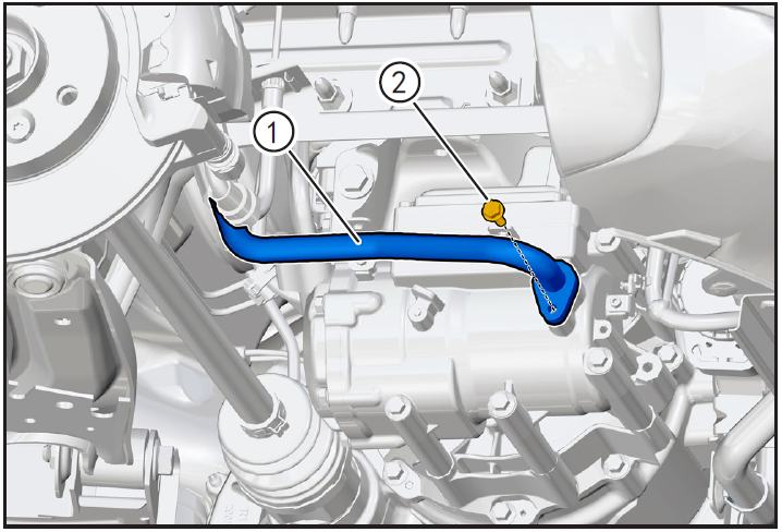
- Remove the fixing bolt ① of the high-pressure pipeline of the electric air-conditioning compressor with a 10mm sleeve, and move the high-pressure pipeline ② of the electric air-conditioning compressor to a non-interference position.
注意!
- There is still a small amount of refrigerant in the air-conditioning pipeline. Protect it before disassembling the air-conditioning pipeline. After disassembling, wipe the spilled refrigerant clean.
- Because of the strong hygroscopicity of air-conditioning refrigerant oil, after removing the air-conditioning pressure switch, plug the joint with a clean cloth sheet.
Disengaging low-pressure wiring harness of electric air-conditioning compressor
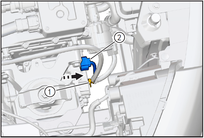
- Use the interior trim removal tool (BBG1102) to detach the low voltage wire harness retaining clip ① of the electric air conditioner compressor.
- Press and hold the lock clip of the low-voltage wiring harness connector of the electric air conditioner compressor, and disengage the low-voltage wiring harness connector of the electric air conditioner compressor ② in the direction of the arrow.
Removing electric air-conditioning compressor
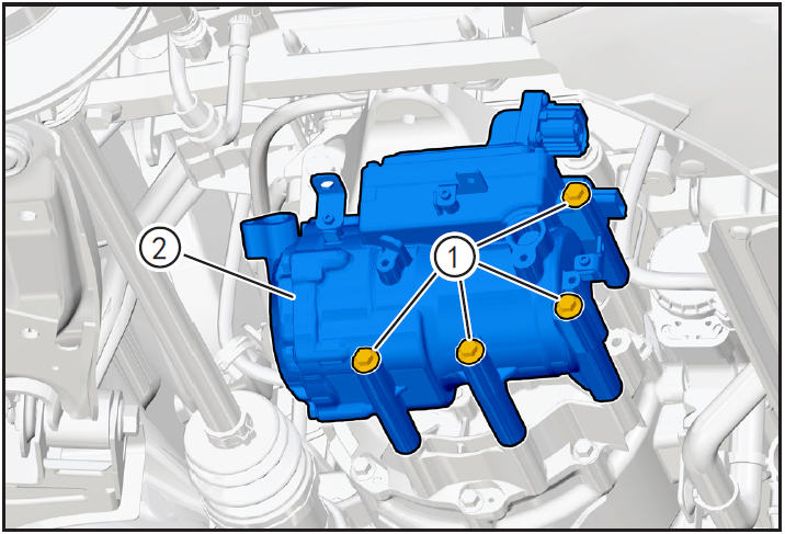
- Use 10mm sleeve to remove the four fixing bolts ① of the electric air-conditioning compressor, and remove the electric air-conditioning compressor ②.
7-Check
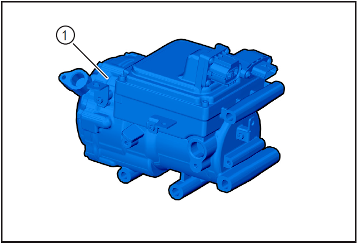
- Check whether the port of the electric air-conditioning compressor ① is blocked or damaged. If so, it is necessary to clean or replace the electric air-conditioning compressor.
8-Installation
Install electric air conditioning compressor
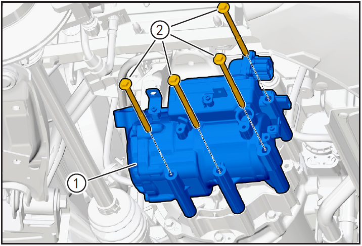
- Move the electric air conditioner compressor ① to the installation position, bring in the fixing bolt ②, and tighten it with a 10mm sleeve with a tightening torque of 25N m.
Installing low pressure wire harness for electric air conditioning compressor
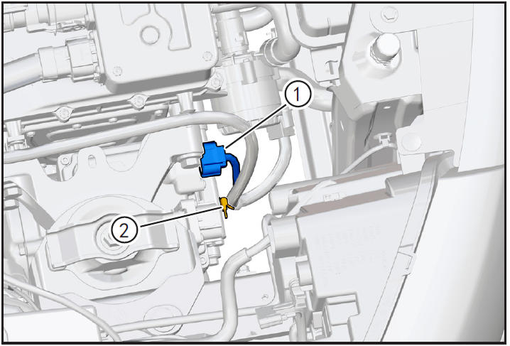
- Install the low voltage wiring harness connector ① of the electric air conditioner compressor until it is installed in place when it hears the "click" sound.
- Clip the low voltage wiring harness fixing card ② of the electric air conditioner compressor into the bracket.
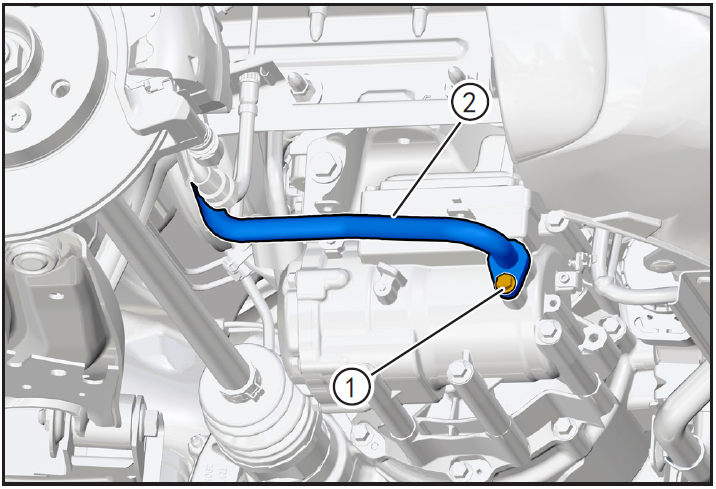
Installing high pressure line of electric air conditioner compressor

- Replace the O-ring of the air conditioning line for installation.
- Before installation, apply a little refrigerant oil to the O-ring of the pipe joint.
- Align the high-pressure pipeline ① of the electric air-conditioning compressor with the electric air-conditioning compressor and install it in place, bring in the fixing bolt ②, and tighten it with a 10mm sleeve with a tightening torque of 8N m.
Installing low pressure line of electric air conditioning compressor
- Replace the O-ring of the air conditioning line for installation.
- Before installation, apply a little refrigerant oil to the O-ring of the pipe joint.
- Align the low-pressure pipeline ① of the electric air-conditioning compressor with the electric air-conditioning compressor and install it in place, bring in the fixing bolt ②, and tighten it with a 10mm sleeve with a tightening torque of 8N m.
Installing ground wire harness for electric air conditioning compressor
- Place electric air-conditioning compressor ground wire harness ① to the installation position, bring in the fixing bolt ②, and tighten with E8 sleeve, tightening torque is 8N · m.
Disassembly of high voltage cable of electric compressor
- Plug the high voltage cable connector ① of the electric air conditioner compressor into place until it hears the "click" sound and is installed in place.
- Lock the locking card (A) of the high voltage cable connector of the electric air conditioning compressor in the direction of the arrow.
- Align the high voltage cable fixing card ① of the electric air conditioner compressor with the installation hole and install it in place.
9-Vehicle high-pressure listing unlocking
- For the following operation of this step, refer to "Locking and Unlocking of Vehicle High Voltage Listing" in the chapter of "Power Battery System"
Install battery positive and negative cables

- Install battery negative cable ① and positive cable ②.
Install maintenance switch
10-Refrigerant filling
Refrigerant filling
- Fill refrigerant and carry out refrigerant leak detection operation. (Refer to "Refrigerant Recovery/Vacuumizing/Filling/Leak Checking" in this section)
11-Clear fault code, check
- After installation, turn the ignition switch to "ON", connect the diagnostic instrument, and clear the fault code.
- Check and confirm that the vehicle is running normally.
- Turn on the ignition switch, operate the air conditioning control panel, check and confirm that all functions of the air conditioning system work normally.
注意!
- Be sure to ensure that the 12V battery voltage is higher than 10V during operation.
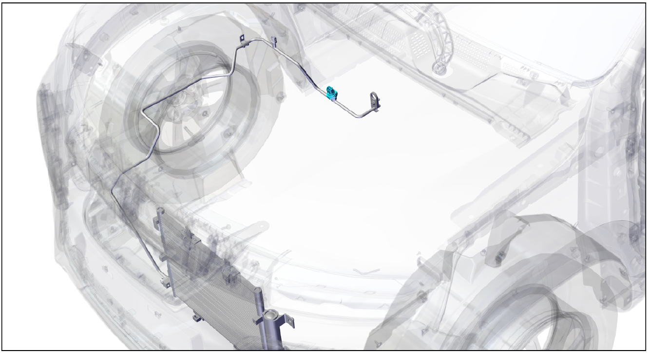
Air conditioning condenser
Disassembly and Installation of Air Conditioner Condenser
1-Part position
The air conditioner condenser is installed inside the front bumper
2-Component structure diagram
3-Protection

Place protective pads at the following positions:
- Front fender;
- Front bumper;
- Driver's seat;
- Carpet (driver's side);
- Steering wheel.
警告!
- Carefully read and master the maintenance precautions in this chapter (refer to "Precautions" in this chapter) before proceeding to the next operation.
4-Recommended Tools
- Internals Removal Tool (BBG1102) [1].
5-Vehicle low voltage circuit locking
- Refer to "Vehicle Low Voltage Circuit Locking and Unlocking" in the chapter "Power Battery System" for the following operation
Vehicle ECU dormancy

- Register electric vehicle information, check instrument indicator light and sleep ECU.
Disconnect the positive and negative cables of the battery
- Disconnect the negative cable ① and positive cable ② of the battery.
注意!
- After disconnecting the negative cable of the battery, pay attention to avoid short connection between positive and negative electrodes.
6-Remove
Refrigerant recovery
- Recovery of refrigerant. (Refer to "Refrigerant Recovery/Vacuumizing/Filling/Leak Checking" in this section)
Front bumper assembly removal
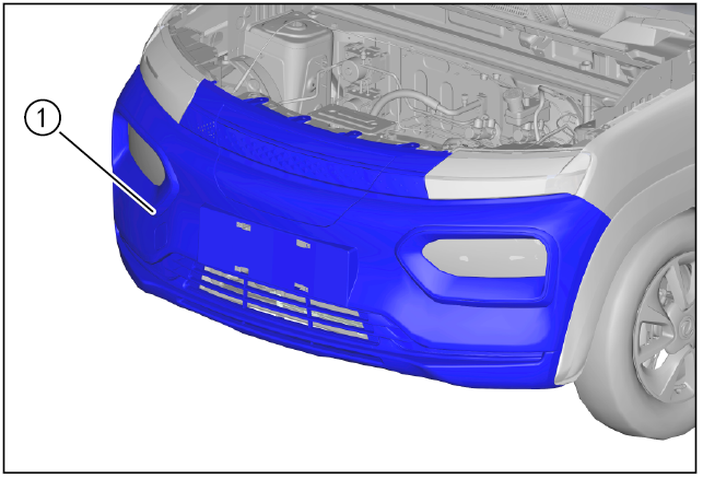
- Remove front bumper assembly ①. (Refer to "Removal and Installation of Front Bumper Assembly" under "Interior and Exterior")
Removing front bumper lower deflector
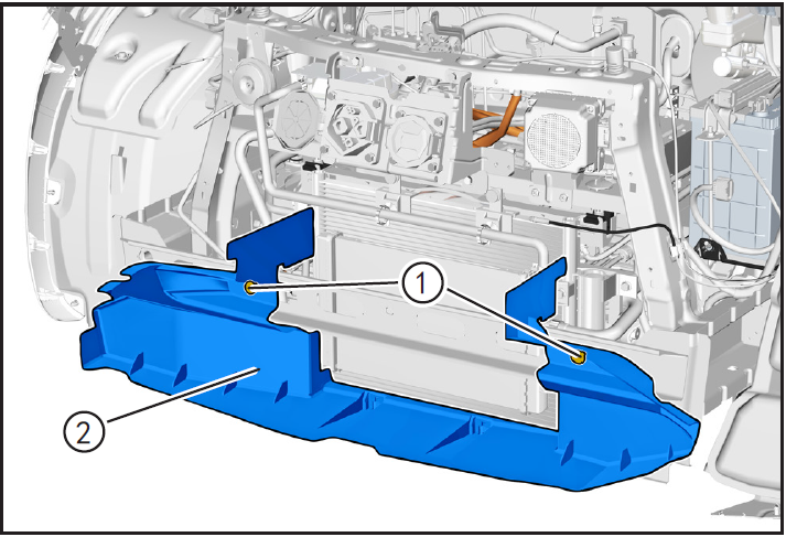
- Remove spoiler retaining card ① using the interior trim removal tool (BBG1102) and remove deflector ②.
Disconnect the air conditioning line

- Remove the fixing bolt ① of air-conditioning high-pressure pipeline (condenser end) with 10mm sleeve, disengage air-conditioning high-pressure pipeline, adjust air-conditioning high-pressure pipeline ② (condenser to expansion valve) and take it out.
注意!
- There is still a small amount of refrigerant in the air-conditioning pipeline. Protect it before disassembling the air-conditioning pipeline. After disassembling, wipe the spilled refrigerant clean.
- Because of the strong hygroscopicity of air-conditioning refrigerant oil, after removing the air-conditioning pipeline, plug the joint with a clean cloth sheet.
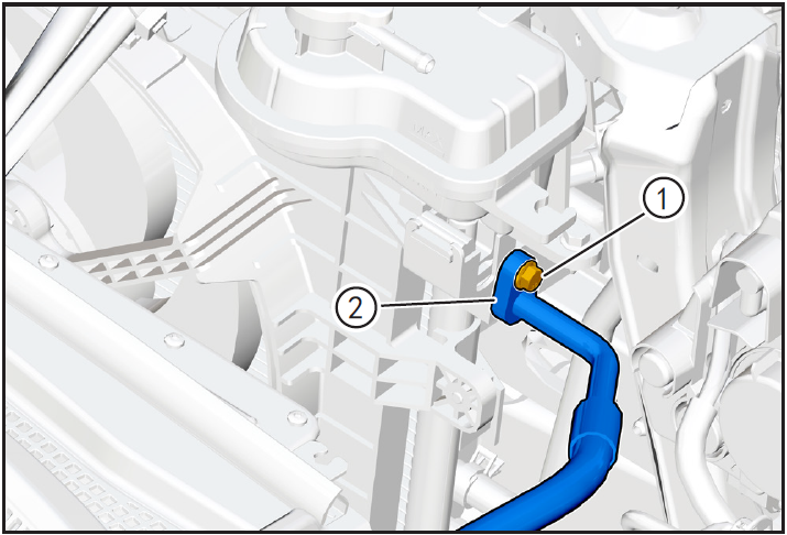
- Remove the fixing bolt ① of high-pressure pipeline (condenser end) with 10mm sleeve, disconnect the high-pressure pipeline ②, and remove the compressor of high-pressure pipeline ② to the condenser.
注意!
- After disconnecting the end of the air-conditioning pipeline, wrap both ends of the pipeline joint with clean cloth sheets.
Disengaging radiator assembly
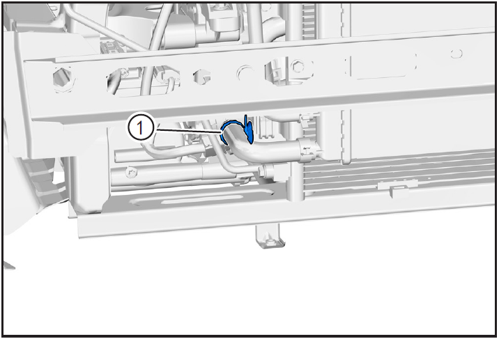
- Use the interior trim removal tool (BBG1102) to detach the radiator outlet line retaining clip ① from the cooling fan.
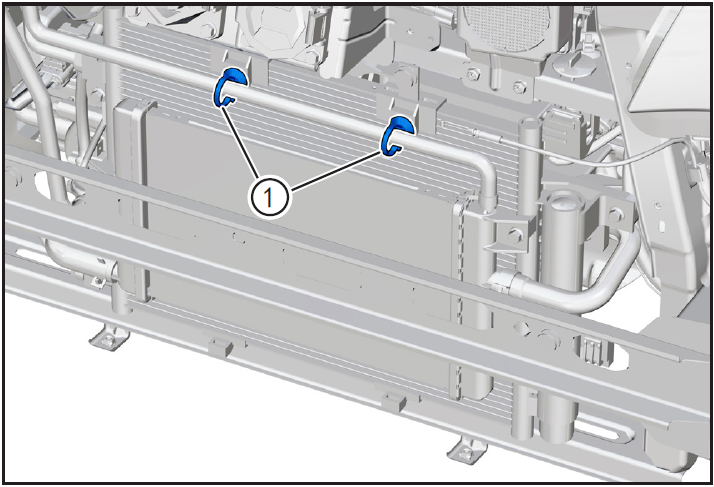
- Use the interior trim removal tool (BBG1102) to detach the cryogenic radiator outlet line retaining clip ①.
- Remove the radiator assembly ① fixing bolt ② (M6 × 12) using a 10mm sleeve and disengage the radiator assembly a certain distance.
注意!
- When removing the air conditioner condenser, the radiator assembly does not need to be removed, but care should be taken to avoid damaging the cooling line or radiator assembly.
Removing condenser
- Remove fast charging cable charging port fixing bolt ① (M6 × 20) using 10mm sleeve.
- Remove the retaining bolt ② (M6 × 20) of the charging port of slow charging cable with 10mm sleeve.
- Use 10mm sleeve to remove the fixing bolt ① (M6 × 20) of the upper bracket of the charging port, and remove the upper bracket ② of the charging port.

- Remove the charging port lower bracket fixing bolt ① (M6 × 20) with a 10mm sleeve, and remove the charging port lower bracket ②.
- Remove the condenser and cooling fan connecting bolts ① (one left and one right) using a 10mm sleeve.
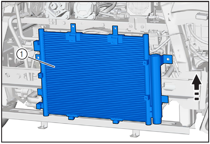
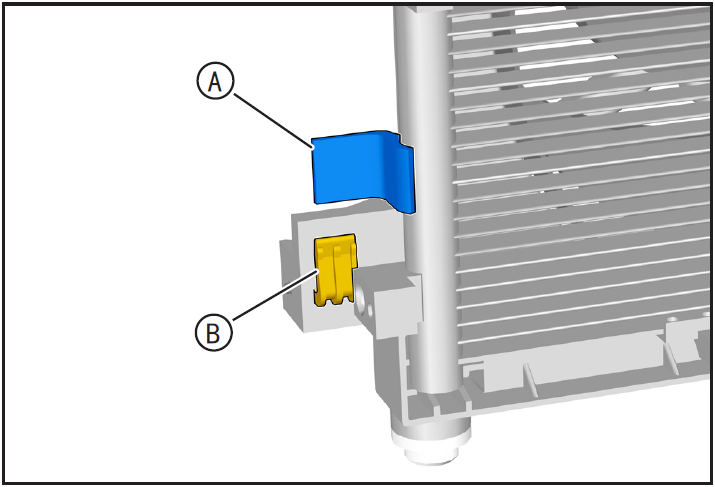
- Lift the condenser assembly ① upward in the direction of the arrow so that the condenser limit pin (A) is disengaged from the cooling fan groove (B).
- Take out condenser assembly ①.
7-Check
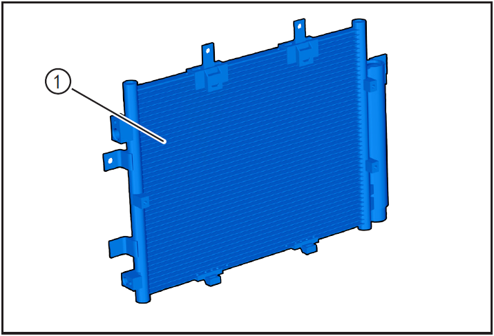
- Check whether the radiator assembly ① is damaged or corroded, and if so, replace it with a new radiator assembly.
8-Installation
Install condenser
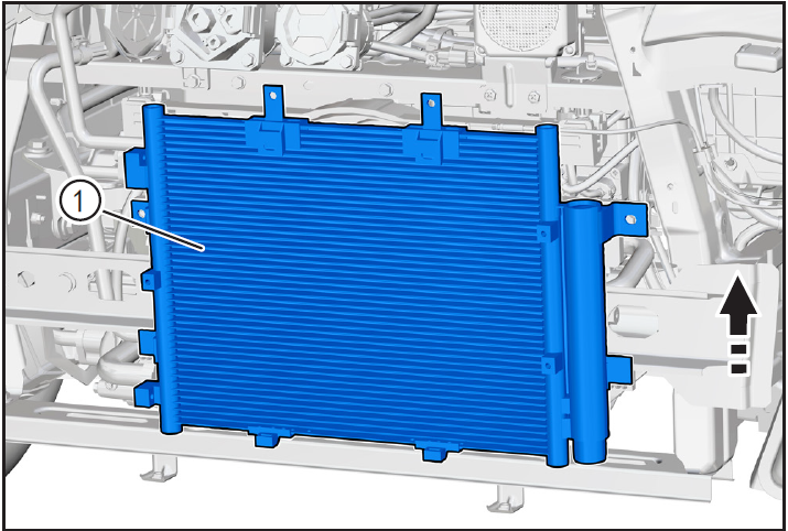
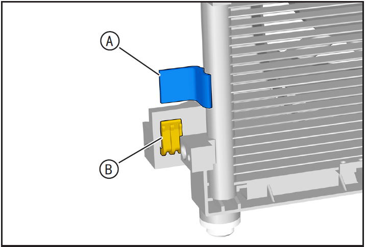
- Place the condenser assembly in the installation position and lift the condenser assembly ① upward in the direction of the arrow so that the condenser limit pin (A) is clamped into the cooling fan groove (B).
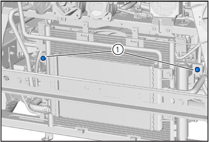
- Install Condenser and Cooling Fan Connection Bolt ① and tighten using 10mm sleeve with tightening torque of 8N · m.
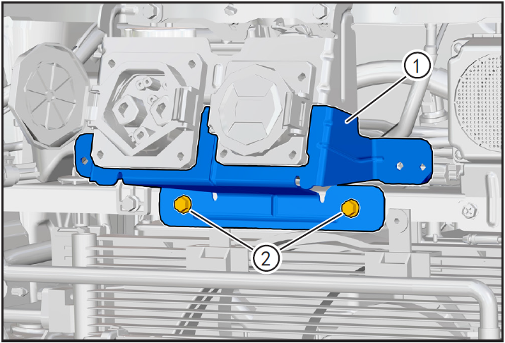
- Place the lower bracket ① of the charging port to the installation position.
- Install the bolt 2 (M6 × 20) for the lower bracket of the charging port and tighten it with a 10mm sleeve with a tightening torque of 8N m.
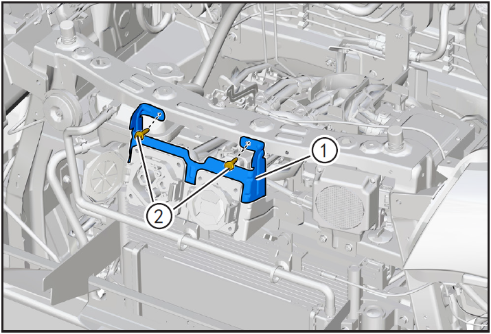
- Align the bracket ① on the charging port with the mounting hole, bring in the fixing bolt ② (M6 × 20), and tighten it with a 10mm sleeve with a tightening torque of 8N m.
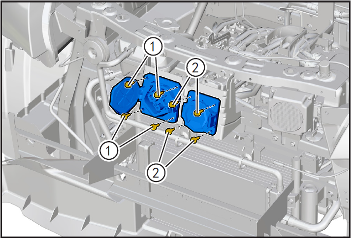
- Align the charging port of the fast charging cable with the mounting hole, bring in the fixing bolt ① (M6 × 20), and tighten it with a 10mm sleeve with a tightening torque of 8N m.
- Align the charging port of slow charging cable with the mounting hole, bring in the fixing bolt ② (M6 × 20), and tighten it with a 10mm sleeve with a tightening torque of 8N m.
Installing radiator assembly
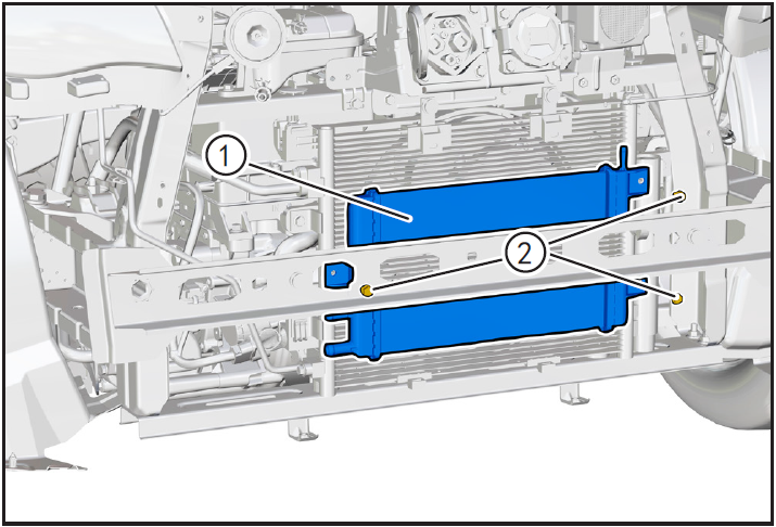
- Align the bolt mounting hole of radiator assembly ① with the condenser bracket and install it in place.
- Screw in fixing bolt ② (M6 × 12) and tighten with 10mm sleeve with tightening torque of 8N m.

- Align the low temperature radiator outlet pipe fixing card ① with the fixing bracket and clip it in place.

- Clip the radiator outlet pipe fixing card ① into the mounting hole on the cooling fan.
Installing air conditioning lines
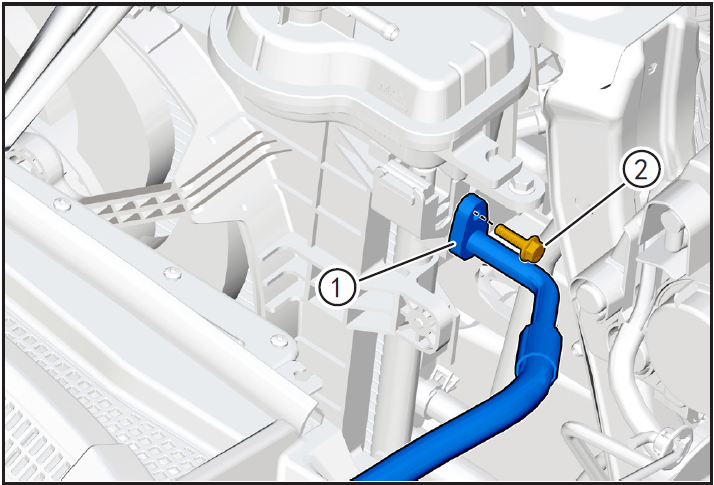
- Replace the O-ring of high-pressure pipeline for installation.
- Before installation, apply a little refrigerant oil to the O-ring of the pipe joint.
- Install the air-conditioning high-pressure pipeline ① aligned with the condenser security end in place, bring in the fixing bolt ② (M6 × 20), and tighten it with a 10mm sleeve with a tightening torque of 8N m.
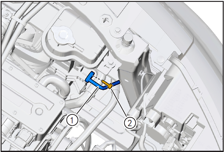
- Replace the new O-ring of air-conditioning high-pressure pipeline for installation.
- Before installation, apply a little refrigerant oil to the O-ring of the pipe joint.
- Install the air-conditioning high-pressure pipeline ① aligned with the condenser end in place, bring in the fixing bolt ② (M6 × 20), and tighten it with a 10mm sleeve with a tightening torque of 8N m.
Installing front bumper lower deflector
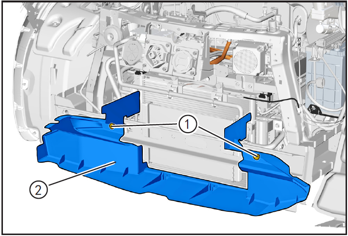
- Place the lower deflector ① at the installation position and install the fixing card ②.
Installing front bumper assembly
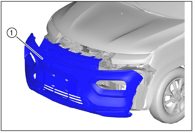
- Install front bumper assembly ①. (Refer to "Removal and Installation of Front Bumper Assembly" under "Interior and Exterior")
9-Vehicle low voltage circuit unlock
- Refer to "Vehicle Low Voltage Circuit Locking and Unlocking" in the chapter "Power Battery System" for the following operation
Install battery positive and negative cables

- Install battery negative cable ① and positive cable ②.
10-Refrigerant filling
Refrigerant filling
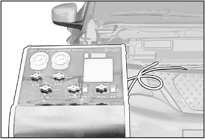
- Fill refrigerant and carry out refrigerant leak detection operation. (Refer to "Refrigerant Recovery/Vacuumizing/Filling/Leak Checking" in this section)
11-Clear fault code, test run
- After installation, turn the ignition switch to "ON", connect the diagnostic instrument, and clear the fault code.
- Check and confirm that the vehicle is running normally.
- Turn on the ignition switch, operate the air conditioning control panel, check and confirm that all functions of the air conditioning system work normally.
注意!
- Be sure to ensure that the 12V battery voltage is higher than 10V during operation.
Disassembly and Installation of Air Conditioning Drying Belt
1-Part position
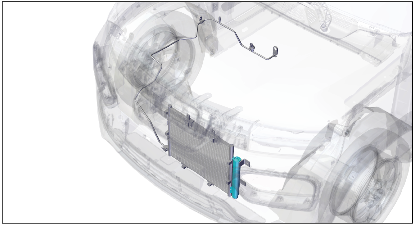
The air conditioner drying bag is installed inside the condenser
2-Component structure diagram
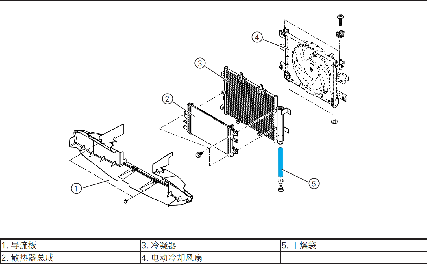
3-Protection
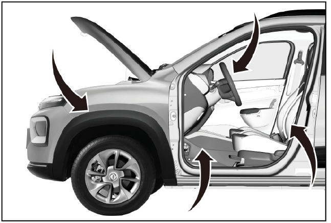
Place protective pads at the following positions:
- Front fender;
- Front bumper;
- Driver's seat;
- Carpet (driver's side);
- Steering wheel.
警告!
- Carefully read and master the maintenance precautions in this chapter (refer to "Precautions" in this chapter) before proceeding to the next operation.
4-Recommended Tools
- Internals Removal Tool (BBG1102) [1].
5-Vehicle low voltage circuit locking
- Refer to "Vehicle Low Voltage Circuit Locking and Unlocking" in the chapter "Power Battery System" for the following operation
Vehicle ECU dormancy

- Register electric vehicle information, check instrument indicator light and sleep ECU.
Disconnect the positive and negative cables of the battery
- Disconnect the negative cable ① and positive cable ② of the battery.
注意!
- After disconnecting the negative cable of the battery, pay attention to avoid short connection between positive and negative electrodes.
6-Remove
Refrigerant recovery
- Recovery of refrigerant. (Refer to "Refrigerant Recovery/Vacuumizing/Filling/Leak Checking" in this section)
Removing condenser

- Remove condenser ①. (Refer to "Condenser Removal and Installation" in this section)
Removing condenser drying bag
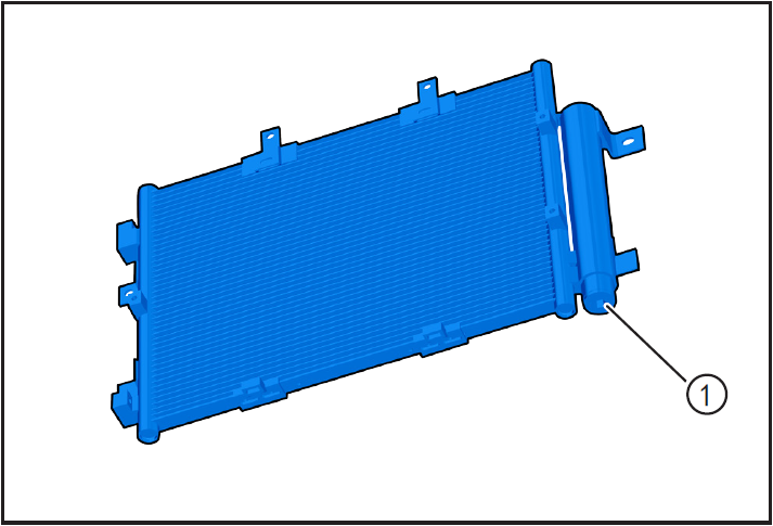
- Remove the dry belt mounting hole bolt ① using the 10mm inner hexagon batch head.
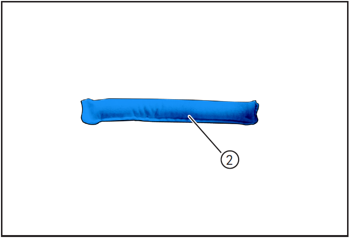
- Use pointed-nosed pliers to remove the drying bag limit pin ① and drying bag ②.
6-Installation
Installing condenser drying bag
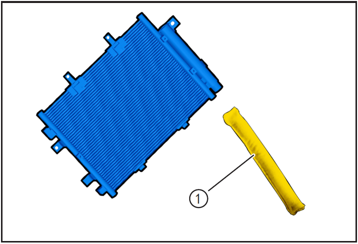
- Replace a new drying bag ① for installation.
- Install the drying bag to the initial position and install the drying bag limit pin.
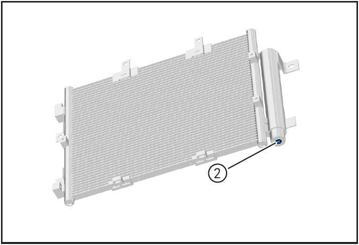
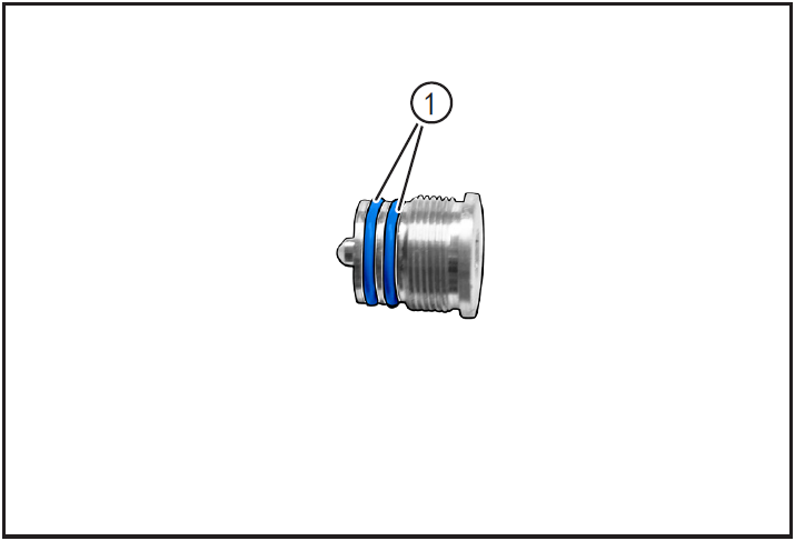
- Replace new bolt sealing ring ①.
- Install dry belt mounting hole bolt ② with 10mm inner hexagon batch head.
Install condenser
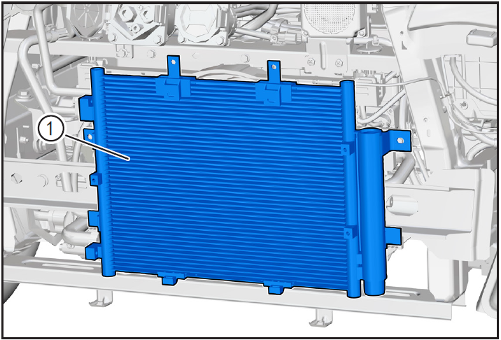
- Install condenser ①. (Refer to "Condenser Removal and Installation" in this section)
7-Vehicle low voltage circuit unlock
- Refer to "Vehicle Low Voltage Circuit Locking and Unlocking" in the chapter "Power Battery System" for the following operation
Install battery positive and negative cables

- Install battery negative cable ① and positive cable ②.
8-Refrigerant filling
Refrigerant filling
- Fill refrigerant and carry out refrigerant leak detection operation. (Refer to "Refrigerant Recovery/Vacuumizing/Filling/Leak Checking" in this section)
9-Clear fault code, test run
- After installation, turn the ignition switch to "ON", connect the diagnostic instrument, and clear the fault code.
- Check and confirm that the vehicle is running normally.
- Turn on the ignition switch, operate the air conditioning control panel, check and confirm that all functions of the air conditioning system work normally.
注意!
- Be sure to ensure that the 12V battery voltage is higher than 10V during operation.
Air conditioning box assembly
Disassembly and installation of air conditioning box assembly
1-Part position
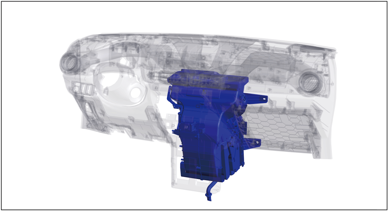
The air conditioning box assembly is installed inside the instrument panel
2-Component structure diagram
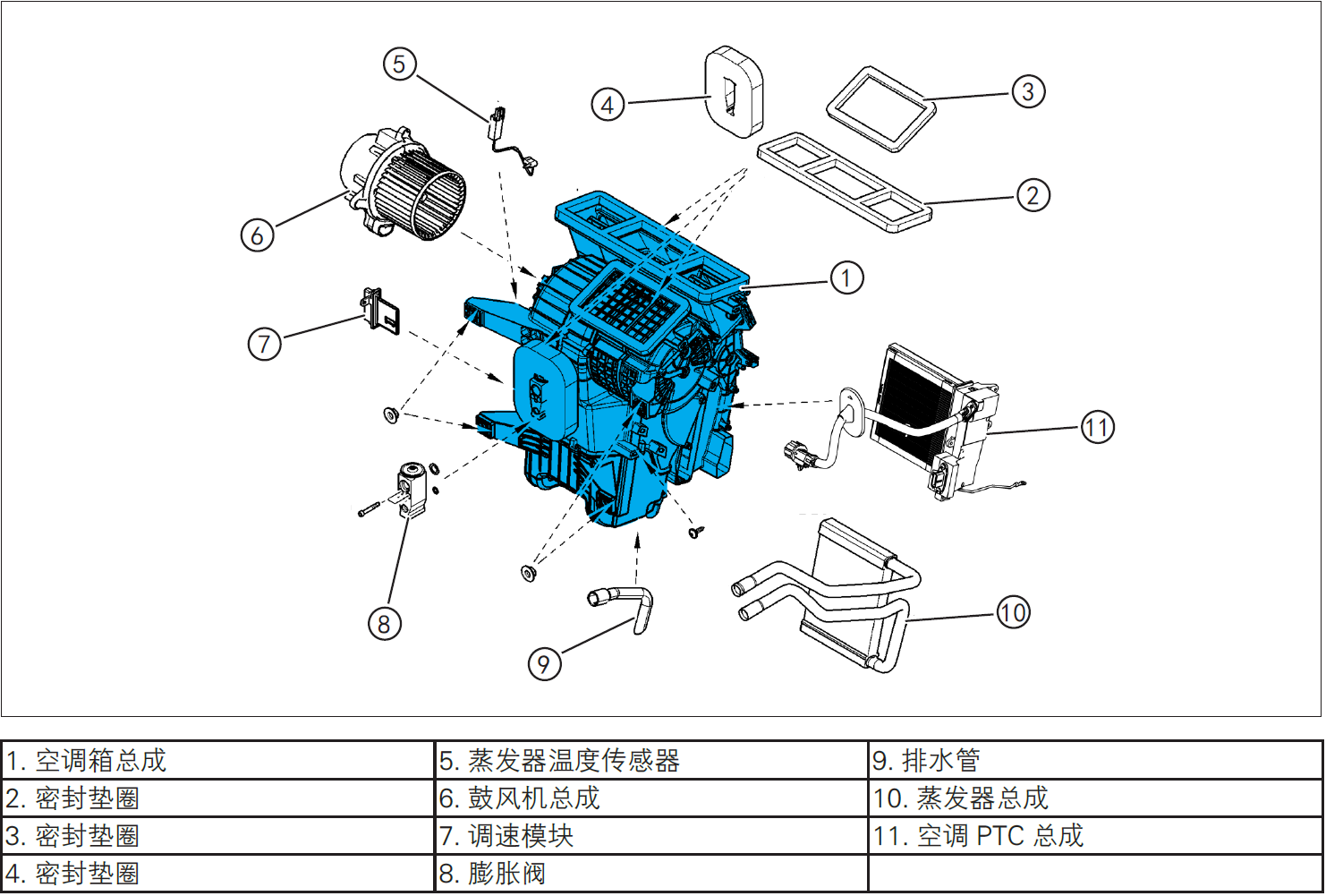
3-Protection
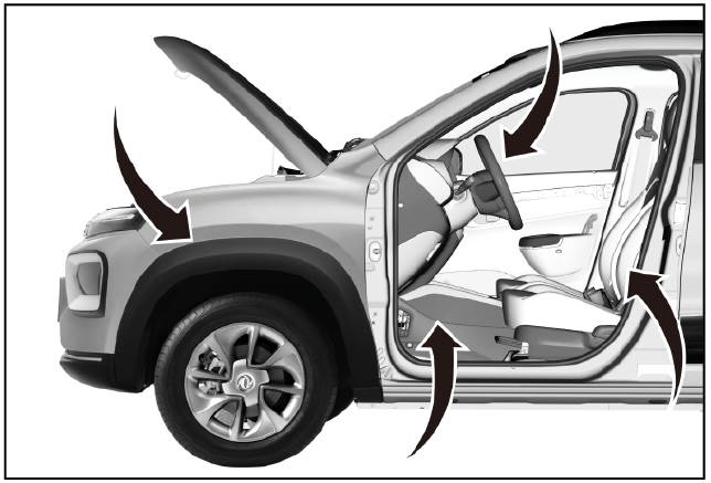
Place protective pads at the following positions:
- Front fender;
- Front bumper;
- Driver's seat;
- Carpet (driver's side);
- Steering wheel.
警告!
- Carefully read and master the maintenance precautions in this chapter (refer to "Precautions" in this chapter) before proceeding to the next operation.
4-Recommended Tools
- Internals Removal Tool (BBG1102) [1].
5-Vehicle low voltage circuit locking
- Refer to "Vehicle Low Voltage Circuit Locking and Unlocking" in the chapter "Power Battery System" for the following operation
Vehicle ECU dormancy

- Register electric vehicle information, check instrument indicator light and sleep ECU.
Remove the service switch
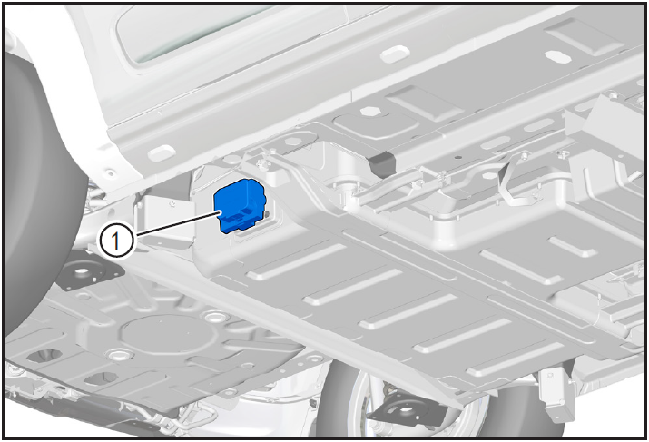
- Remove service switch ①.
Disconnect the positive and negative cables of the battery
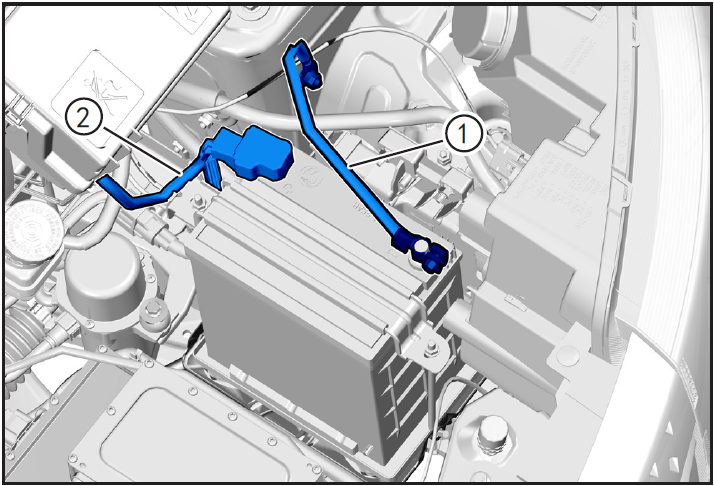
- Disconnect the negative cable ① and positive cable ② of the battery.
注意!
- After disconnecting the negative cable of the battery, pay attention to avoid short connection between positive and negative electrodes.
Zero voltage test
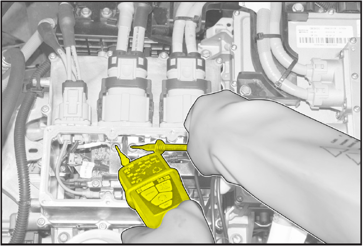
- Use VAT test meter to measure the terminal. If the voltage is 0V, it shows that the high-voltage system is discharged and there is no high voltage;
- If the voltage is not 0V, do not carry out maintenance operation, otherwise high voltage electric shock may occur, wait for the voltage to be 0V before carrying out maintenance operation.
6-Remove
Refrigerant recovery

- Recovery of refrigerant. (Refer to "Refrigerant Recovery/Vacuumizing/Filling/Leak Checking" in this section)
Removing expansion valve
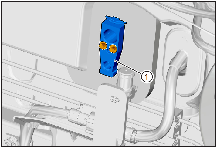
- Remove air conditioning expansion valve ①. (Refer to "Removal and Installation of Air Conditioning Expansion Valves" in this section.)
Removing instrument panel assembly
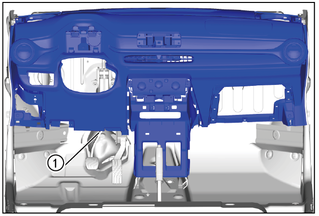
- Remove the instrument panel assembly ①. (Refer to "Instrument Panel Assembly Removal and Installation" in "Instrument Panel" section)
Removing instrument panel frame
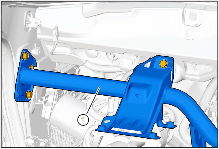
- Remove the instrument panel frame ①. (Refer to "Dashboard Frame Removal and Installation" in "Dashboard" Systems.)
Removing air conditioning box assembly
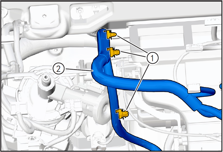
- Use the interior trim removal tool (BBG1102) to detach the wiring harness snap ① on the air conditioning box assembly and move the wiring harness ② to the non-interference position.
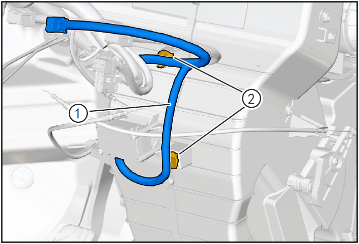
- Use the interior trim removal tool (BBG1102) to disengage the dashboard wiring harness ① retaining clip ② on the air conditioning box assembly.
- Press and hold PM2.5 dust sensor connector locking clip (A) to disengage PM2.5 dust sensor connector ①.
- Use the interior trim removal tool (BBG1102) to detach the low voltage wire harness ① retaining clip ②.

- Press and hold the LV harness connector lock card (A) of the air conditioning PTC assembly and disconnect the LV harness connector ① of the air conditioning PTC assembly.
- Remove the air-conditioning PTC ground harness nut ① using a 10mm sleeve and disengage the air-conditioning PTC ground harness ②.

- Use the interior trim removal tool (BBG1102) to detach the air conditioning PTC high voltage cable retaining card ①.
- Remove the air-conditioning PTC assembly fixing screw ② using the cross lift, and disengage the air-conditioning PTC assembly ③ from the air-conditioning box assembly in the direction of the arrow.
注意!
- Move the PTC assembly of the air conditioner to a non-interference position.
- Use the interior trim removal tool (BBG1102) to disengage the dashboard wiring harness ① retaining clip ② on the air conditioning box assembly.
- Press and hold the lock card of the adjustable speed module connector and disconnect the adjustable speed module connector ③.
- Press and hold the Evaporator Temperature Sensor Connector Locking Card and disconnect Evaporator Temperature Sensor Connector ④.
- Press and hold the blower connector locking card and disconnect the blower connector ⑤.
- Tidy the dashboard wiring harness and move it to a non-interference position.


- Remove the air-conditioning box assembly fixing nut ① using a 10mm sleeve, and remove the air-conditioning box assembly ②.
7-Check
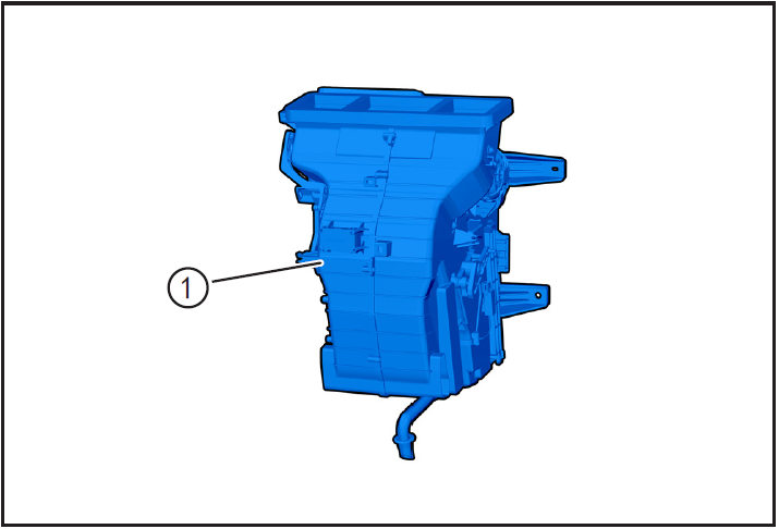
- Check whether the air conditioning box assembly ① is damaged, and if so, replace it with a new one for installation.
8-Installation
Installing air conditioning box assembly

- Put the air-conditioning box assembly ① to the installation position, and install the fixing nut ② of the air-conditioning box assembly. After all the fixing bolts are installed, tighten the fixing nut with a 10mm sleeve with a tightening torque of 8N m.
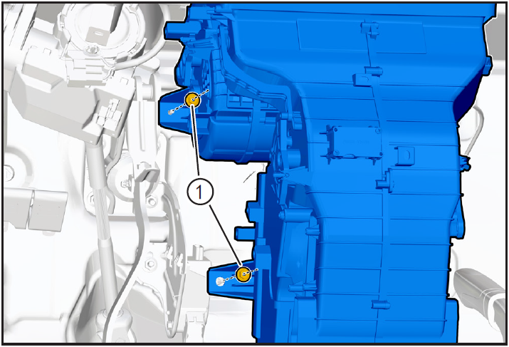
- Install retaining nut ① and tighten using a 10mm sleeve with a tightening torque of 8N · m.
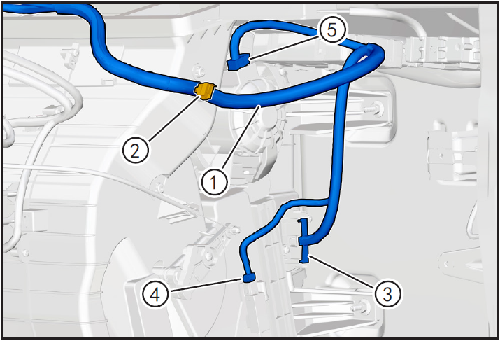
- Finish the dashboard wiring harness ① and restore it to the initial installation position.
- Clip the dashboard wiring harness retaining card ② into the fixed air conditioning box assembly.
- Install the adjustable speed module connector ③ until you hear the "click" sound and install it in place.
- Install the evaporator temperature sensor connector ④ until you hear the "click" sound and install it in place.
- Install the blower connector ⑤ until you hear the "click" sound and install it in place.

- Install the air conditioning PTC assembly ① to the air conditioning box assembly in the direction of the arrow.
- Install the fixing screw ② of the PTC assembly of the air conditioner and tighten it with a cross lift. The tightening torque is.
- Install air conditioning PTC high voltage cable fixing card ③.
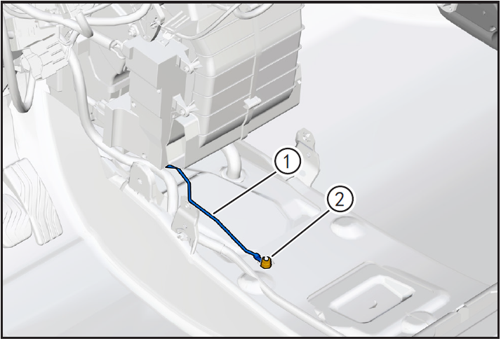
- Position air conditioning PTC ground harness ① to installation position, install using 10mm sleeve and tighten PTC ground harness fixing nut ② with tightening torque of 8N · m.
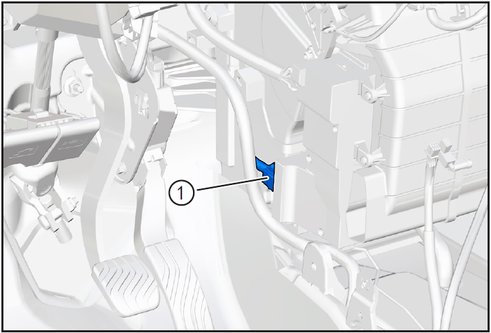
- Install low voltage wiring harness connector ① of air conditioning PTC assembly until "click" sound is heard and installed in place.
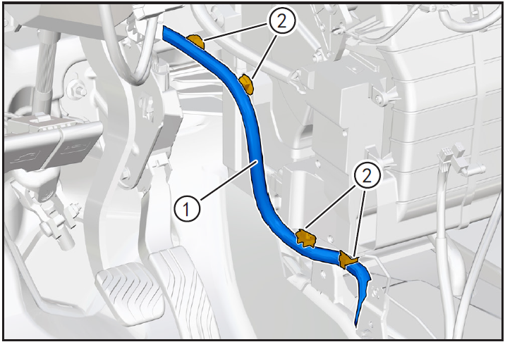
- The fixing card ② of low voltage wire harness ① is clamped into the fixing mounting hole.
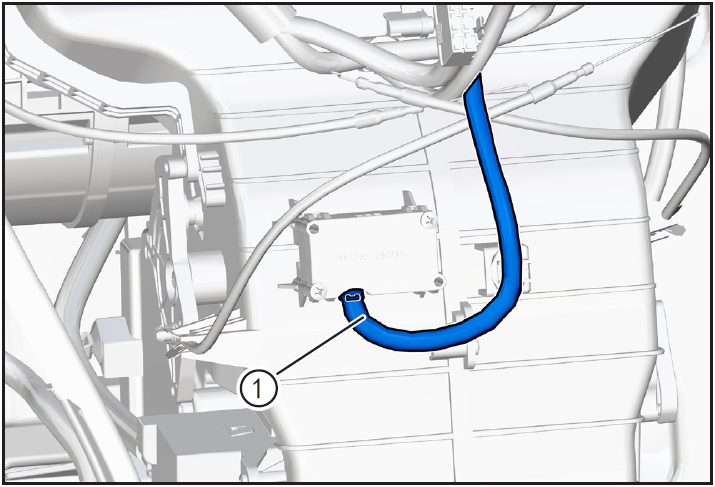
- Install PM2.5 dust sensor connector ① until "click" sound is heard and installed in place.
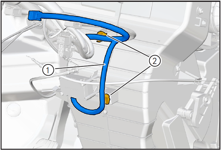
- Clip the dashboard wiring harness ① fixing card ② into the air conditioning box assembly.

- Clip the dashboard wiring harness ① fixing card ② into the air conditioning box assembly.
Installing instrument panel frame

- Install the dashboard frame ①. (Refer to "Dashboard Frame Removal and Installation" in "Dashboard" Systems.)
Installing the instrument panel assembly

- Install the instrument panel assembly ①. (Refer to "Instrument Panel Assembly Removal and Installation" in this section)
Installing expansion valve
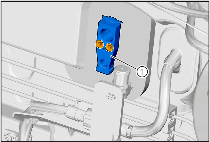
- Remove air conditioning expansion valve ①. (Refer to "Removal and Installation of Air Conditioning Expansion Valves" in this section.)
9-Vehicle high voltage circuit unlock
- Refer to "Vehicle High Voltage Circuit Locking and Unlocking" in the chapter "Power Battery System" for the following operation
Install battery positive and negative cables

- Install battery negative cable ① and positive cable ②.
Install maintenance switch

- Install maintenance switch ①.
10-Refrigerant filling
Refrigerant filling
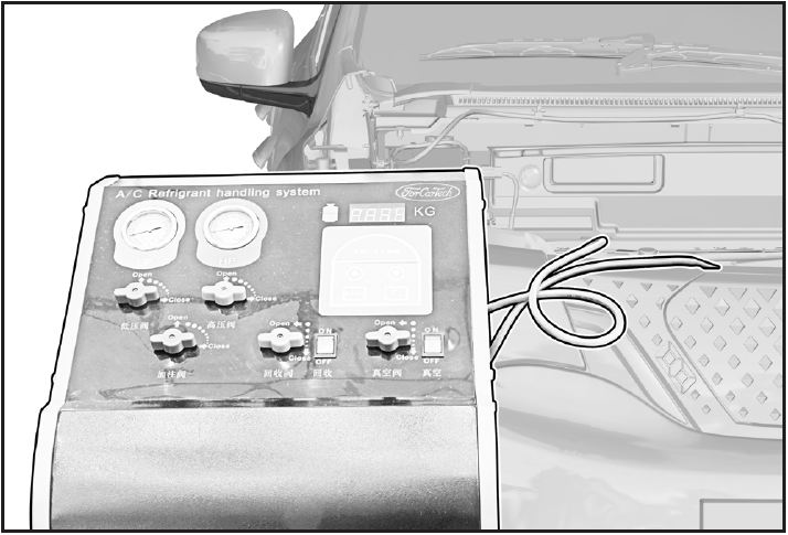
- Fill refrigerant and carry out refrigerant leak detection operation. (Refer to "Refrigerant Recovery/Vacuumizing/Filling/Leak Checking" in this section)
11-Clear fault code, check
- After installation, turn the ignition switch to "ON", connect the diagnostic instrument, and clear the fault code.
- Check and confirm that the vehicle is running normally.
- Turn on the ignition switch, operate the air conditioning control panel, check and confirm that all functions of the air conditioning system work normally.
注意!
- Be sure to ensure that the 12V battery voltage is higher than 10V during operation.
PTC heating plate
Disassembly and installation of PTC heating plate of air conditioner
1-Part position
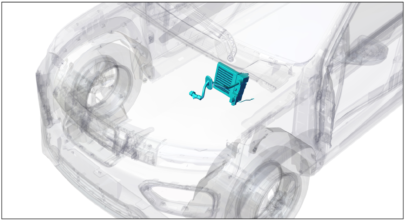
The PTC heating plate of the air conditioner is installed inside the instrument panel and in the air conditioner box assembly
2-Component structure diagram
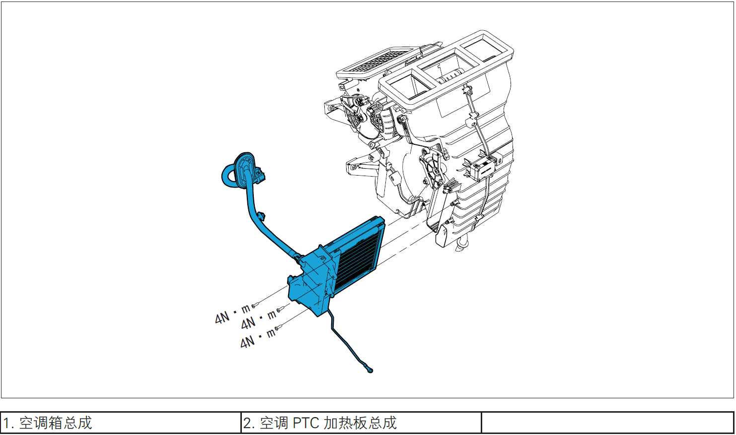
3-Protection
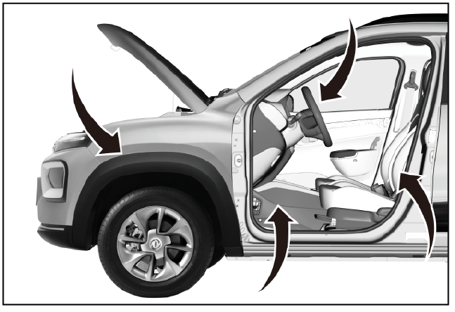
Place protective pads at the following positions:
- Front fender;
- Front bumper;
- Driver's seat;
- Carpet (driver's side);
- Steering wheel.
警告!
- Carefully read and master the maintenance precautions in this chapter (refer to "Precautions" in this chapter) before proceeding to the next operation.
4-Recommended Tools
- Internals Removal Tool (BBG1102) [1].
5-Vehicle low voltage circuit locking
- Refer to "Vehicle Low Voltage Circuit Locking and Unlocking" in the chapter "Power Battery System" for the following operation
Vehicle ECU dormancy

- Register electric vehicle information, check instrument indicator light and sleep ECU.
Remove the service switch

- Remove service switch ①.
Disconnect the positive and negative cables of the battery

- Disconnect the negative cable ① and positive cable ② of the battery.
注意!
- After disconnecting the negative cable of the battery, pay attention to avoid short connection between positive and negative electrodes.
Zero voltage test
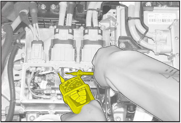
- Use VAT test meter to measure the terminal. If the voltage is 0V, it shows that the high-voltage system is discharged and there is no high voltage;
- If the voltage is not 0V, do not carry out maintenance operation, otherwise high voltage electric shock may occur, wait for the voltage to be 0V before carrying out maintenance operation.
6-Remove
Removing instrument panel assembly
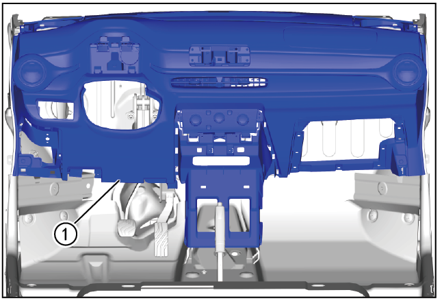
- Remove the instrument panel assembly ①. (Refer to "Instrument Panel Assembly Removal and Installation" in "Instrument Panel" section)
Removing instrument panel frame

- Remove the instrument panel frame ①. (Refer to "Dashboard Frame Removal and Installation" in "Dashboard" Systems.)
Disengage the connector of PTC heating plate of air conditioner
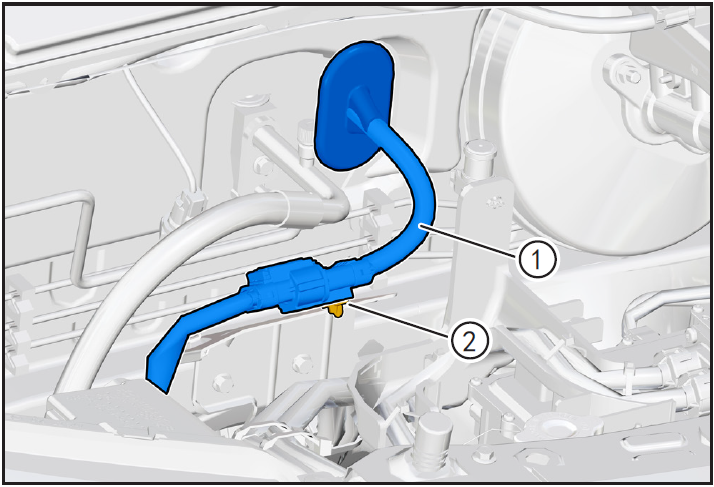
- Use the interior trim removal tool (BBG1102) to detach the air conditioner PTC high voltage cable ① retaining card ②.


- Disengage the HV cable connector locking clamp (A) of the air conditioning PTC HV cable in the direction of the arrow, press and hold the HV cable connector locking clamp (B), and disengage the HV cable connector ①.
- Move the air conditioner PTC high voltage cable from the powertrain cabin to the cockpit.
Removing PTC heating plate of air conditioner
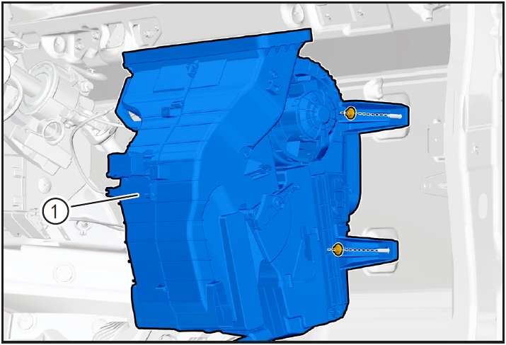
- Loosen the 4 fixing bolts of the air conditioning box assembly ① using a 10mm sleeve.
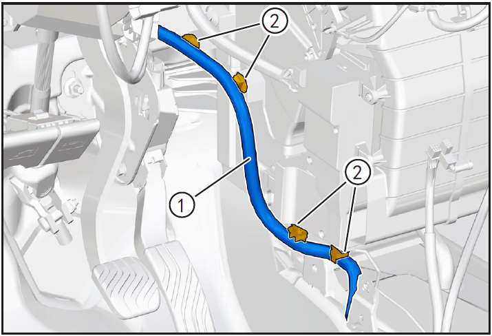
- Use the interior trim removal tool (BBG1102) to detach the low voltage wire harness ① retaining clip ②.
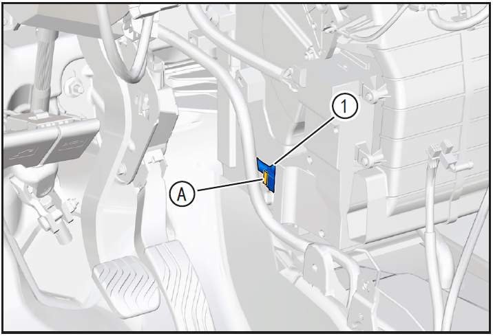
- Press and hold the LV harness connector lock card (A) of the air conditioning PTC assembly and disconnect the LV harness connector ① of the air conditioning PTC assembly.
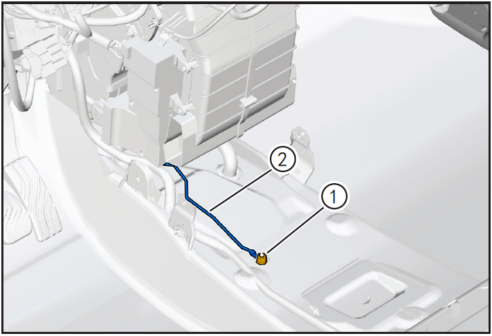
- Remove the air-conditioning PTC ground harness nut ① using a 10mm sleeve and disengage the air-conditioning PTC ground harness ②.
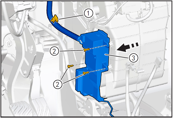
- Use the interior trim removal tool (BBG1102) to detach the air conditioning PTC high voltage cable retaining card ①.
- Remove the air-conditioning PTC assembly fixing screw ② by using the cross lift, detach the air-conditioning PTC assembly from the air-conditioning box, and remove the air-conditioning PTC assembly ③ in the direction of the arrow.
7-Check
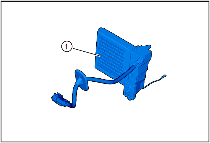
- Check whether the PTC heating plate ① is damaged and whether the pins are corroded. If so, replace it with a new one for installation.
8-Installation
Installing PTC heating plate for air conditioning
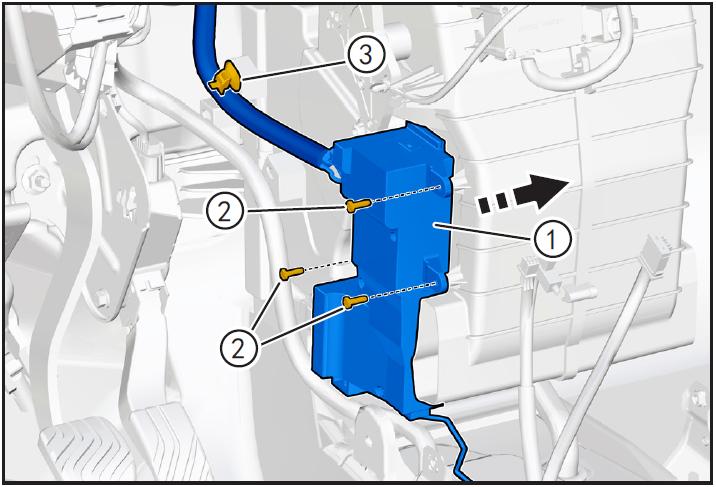
- Put the air conditioning PTC assembly ① to the installation position, and move the air conditioning PTC high voltage cable connector to the powertrain cabin.
- Install the air conditioner PTC assembly fixing screw ② and tighten with a cross lifting torque of 4N · m.
- Clip the air conditioner PTC high voltage cable fixing card ③ into the fixing installation hole.
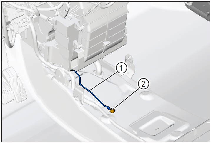
- Move the air conditioning PTC ground wire harness ① to the installation position, install the retaining nut ② and tighten using a 10mm sleeve with a tightening torque of 10N · m.
- Install low voltage wiring harness connector ① of air conditioning PTC assembly until "click" sound is heard and installed in place.

- The fixing card ② of low voltage wire harness ① is clamped into the fixing mounting hole.

- Tighten 4 fixing bolts of air conditioning box assembly ① using 10mm sleeve.
- PTC HV Cable HV Cable Connector ① Plug into position until you hear the "click" sound and install it in place.
- Lock the locking card (A) of the high voltage cable connector of the electric air conditioning compressor in the direction of the arrow.
- The fixing card ② of PTC high voltage cable of air conditioner is clamped into the fixing installation hole.
Installing instrument panel frame
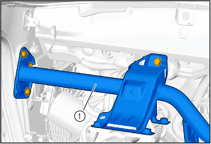
- Install the dashboard frame ①. (Refer to "Dashboard Frame Removal and Installation" in "Dashboard" Systems.)
Installing the instrument panel assembly
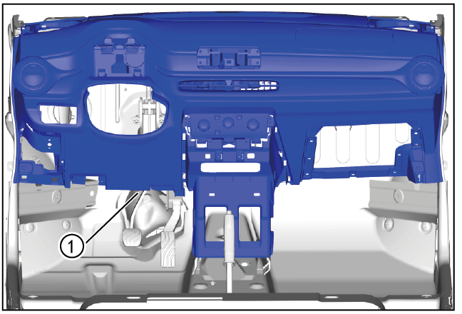
- Install the instrument panel assembly ①. (Refer to "Instrument Panel Assembly Removal and Installation" in this section)
9-Vehicle high voltage circuit unlock
- Refer to "Vehicle High Voltage Circuit Locking and Unlocking" in the chapter "Power Battery System" for the following operation
Install battery positive and negative cables
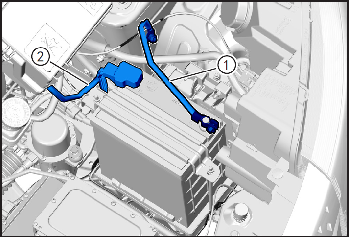
- Install battery negative cable ① and positive cable ②.
Install maintenance switch
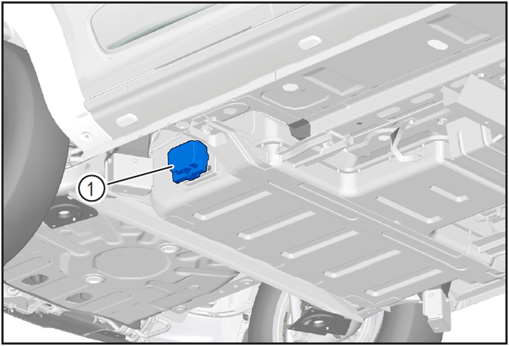
- Install maintenance switch ①.
10-Clear fault code, test run
- After installation, turn the ignition switch to "ON", connect the diagnostic instrument, and clear the fault code.
- Check the air conditioning system to make sure the vehicle is running normally.
- Remove safety warning fences and warning signs.
PM2.5 dust sensor
Removal and installation of PM2.5 dust sensor
1-Part position
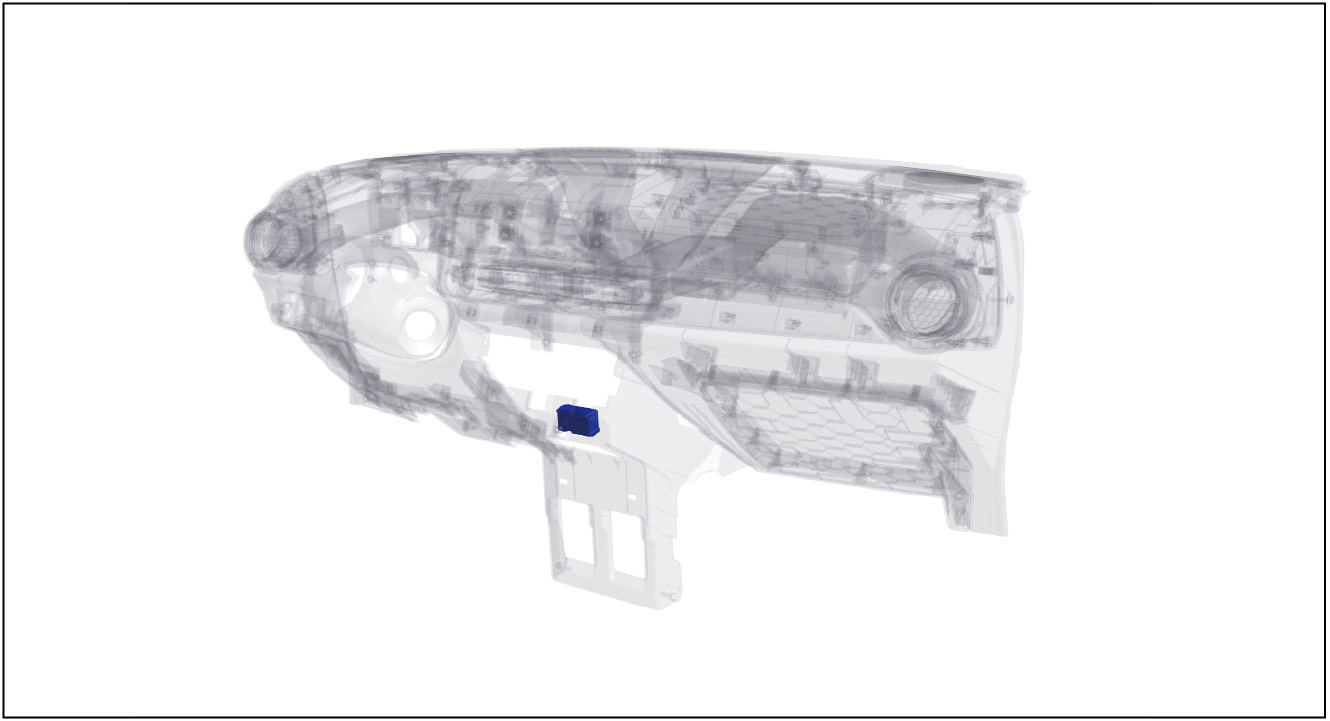
The PM2.5 dust sensor is installed on the inner side of the instrument panel and the air conditioning box assembly
2-Component structure diagram
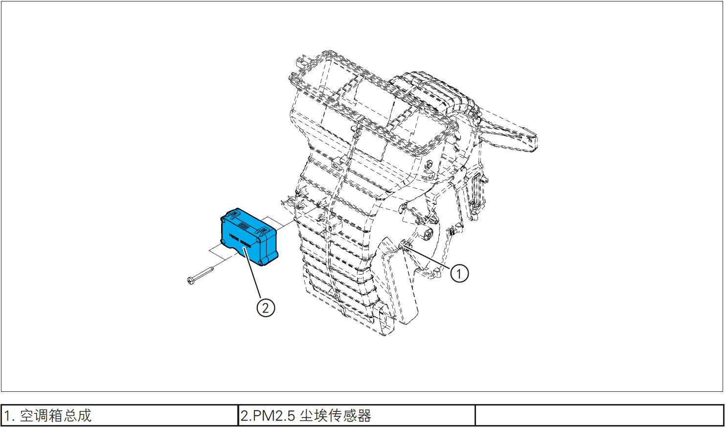
3-Protection

Place protective pads at the following positions:
- Front fender;
- Front bumper;
- Driver's seat;
- Carpet (driver's side);
- Steering wheel.
警告!
- Carefully read and master the maintenance precautions in this chapter (refer to "Precautions" in this chapter) before proceeding to the next operation.
4-Vehicle low voltage circuit locking
- Refer to "Vehicle Low Voltage Circuit Locking and Unlocking" in the chapter "Power Battery System" for the following operation
Vehicle ECU dormancy

- Register electric vehicle information, check instrument indicator light and sleep ECU.
Disconnect the positive and negative cables of the battery

- Disconnect the negative cable ① and positive cable ② of the battery.
注意!
- After disconnecting the negative cable of the battery, pay attention to avoid short connection between positive and negative electrodes.
5-Remove
Removing instrument panel assembly
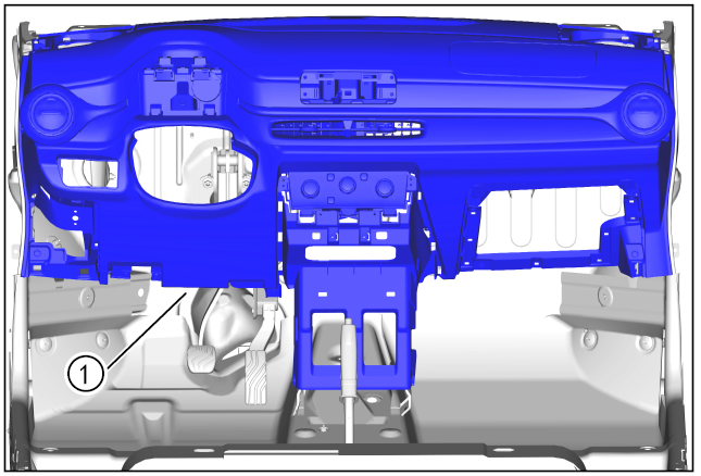
- Remove the instrument panel assembly ①. (Refer to "Instrument Panel Assembly Removal and Installation" in this section)
Removing PM2.5 dust sensor
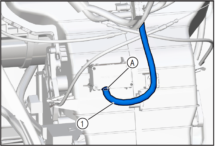
- Press and hold PM2.5 dust sensor connector locking clip (A) to disengage PM2.5 dust sensor connector ①.
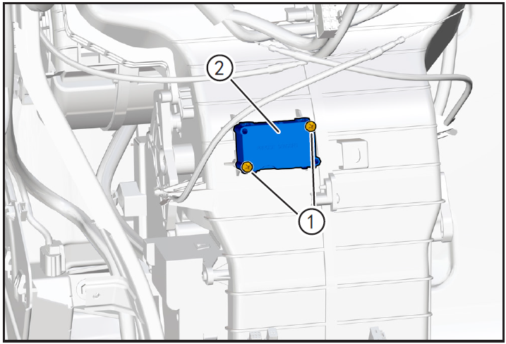
- Remove PM2.5 dust sensor fixing screws ① using the cross lift and remove PM2.5 dust sensor ②.
6-Check
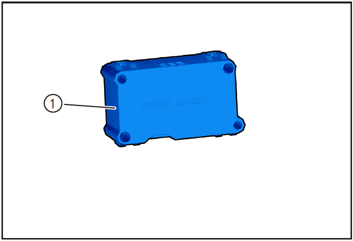
- Check whether PM2.5 dust sensor ① is damaged and whether the pins are corroded. If so, replace it with a new one for installation.
7-Installation
Install PM2.5 dust sensor
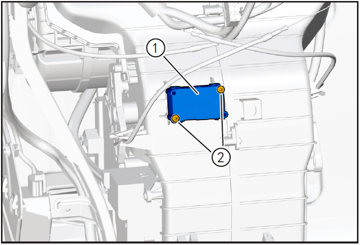
- Place PM2.5 dust sensor ① to the installation position, install the fixing screw ②, and tighten it with a cross.
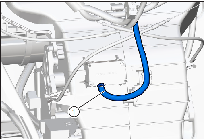
- Install PM2.5 dust sensor connector ① until "click" sound is heard and installed in place.
Installing the instrument panel assembly
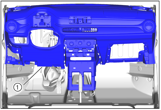
- Install the instrument panel assembly ①. (Refer to "Instrument Panel Assembly Removal and Installation" in this section)
8-Vehicle low voltage circuit unlock
- Refer to "Vehicle Low Voltage Circuit Locking and Unlocking" in the chapter "Power Battery System" for the following operation
Install battery positive and negative cables

- Install battery negative cable ① and positive cable ②.
9-Clear fault code, check
- After installation, turn the ignition switch to "ON", connect the diagnostic instrument, and clear the fault code.
- Remove safety warning fences and warning signs.
Air conditioning evaporator
Disassembly and Installation of Air Conditioning Evaporator Assembly
1-Part position
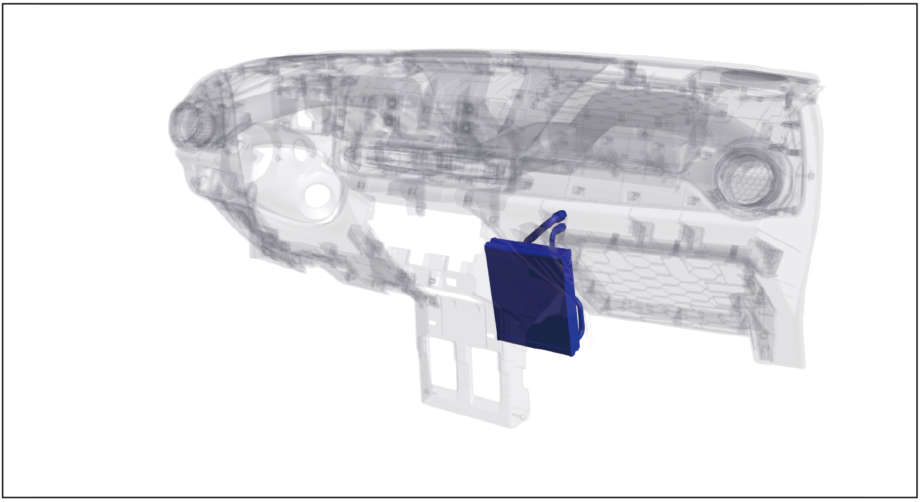
The air conditioner evaporator assembly is installed inside the instrument panel and in the air conditioner box assembly
2-Component structure diagram
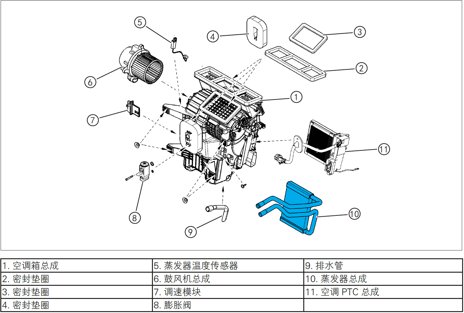
3-Protection
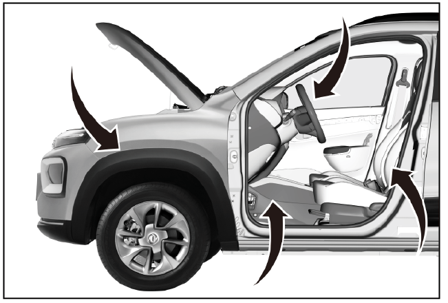
Place protective pads at the following positions:
- Front fender;
- Front bumper;
- Driver's seat;
- Carpet (driver's side);
- Steering wheel.
警告!
- Carefully read and master the maintenance precautions in this chapter (refer to "Precautions" in this chapter) before proceeding to the next operation.
4-Vehicle low voltage circuit locking
- Refer to "Vehicle Low Voltage Circuit Locking and Unlocking" in the chapter "Power Battery System" for the following operation
Vehicle ECU dormancy

- Register electric vehicle information, check instrument indicator light and sleep ECU.
Disconnect the positive and negative cables of the battery
- Disconnect the negative cable ① and positive cable ② of the battery.
注意!
- After disconnecting the negative cable of the battery, pay attention to avoid short connection between positive and negative electrodes.
5-Remove
Removing air conditioning box assembly

- Remove air conditioning box assembly ①. (Refer to "Removal and Installation of Air Conditioning Box Assembly" in this section)
Removing blower assembly
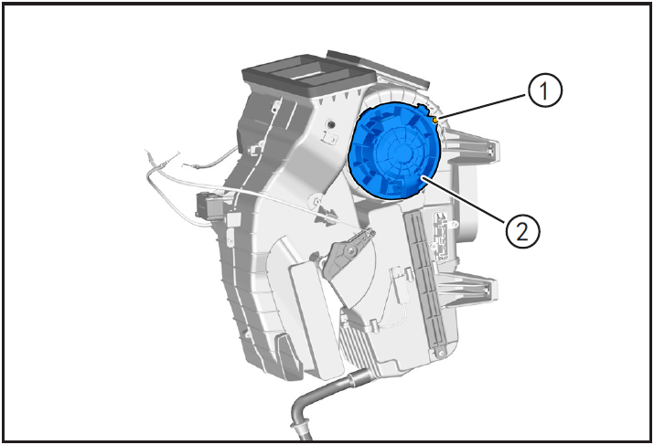
- Remove the blower assembly fixing screw ① using the cross lift and rotate clockwise in the direction of the arrow to remove the blower assembly ②.
Removing filter element of air conditioner filter
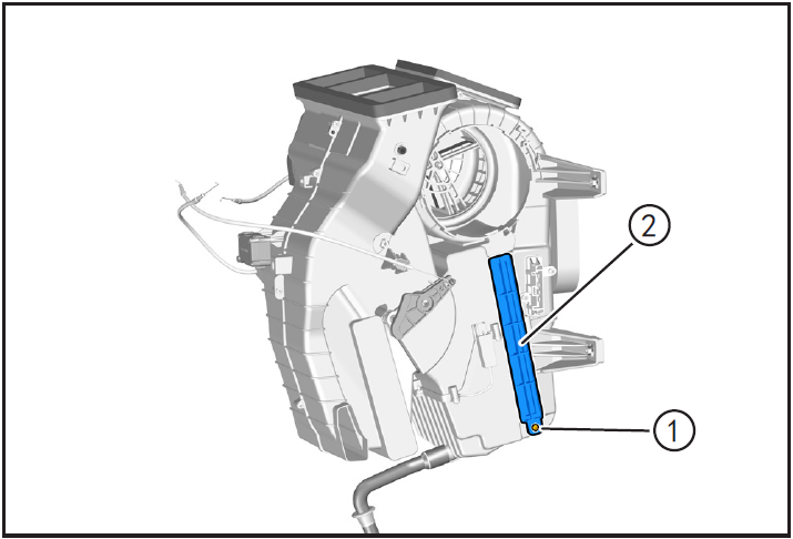
- Remove the air conditioner filter cover fixing screw ① using the cross lift, and remove the air conditioner filter cover.
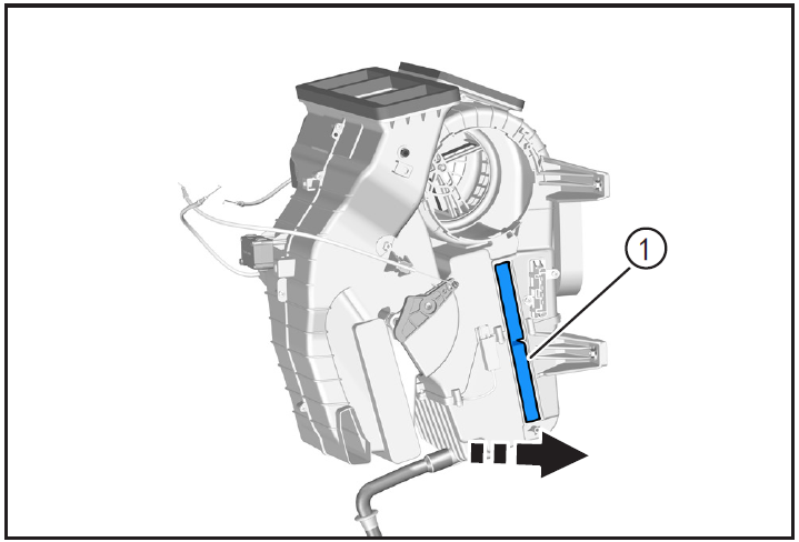
- Take out the air conditioner filter element ① in the direction of arrow.
Removing speed control module

- Remove the fixing screw ① of the speed regulating module by using the cross lift, and take the speed regulating module ②.
Removing evaporator assembly
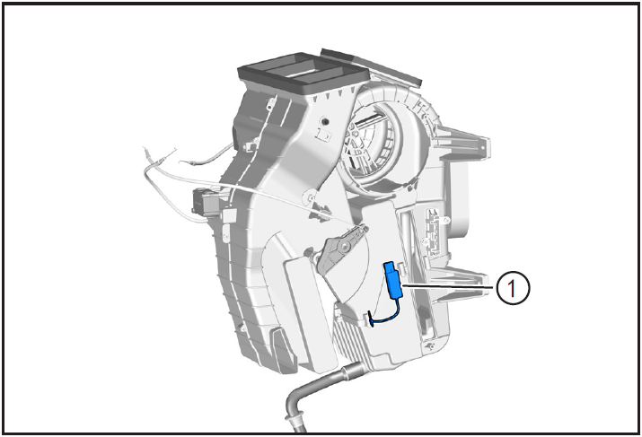
- Slide in the direction of the arrow to detach the evaporator temperature sensor socket ① from the air conditioning box assembly retaining card.
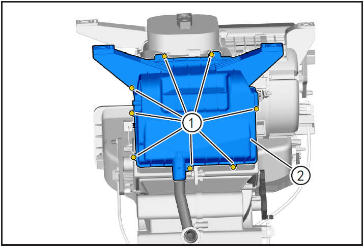
- Remove the 8 fixing screws ① of the lower housing of the air-conditioning box assembly using the cross lift, and remove the lower housing of the air-conditioning box assembly ②.
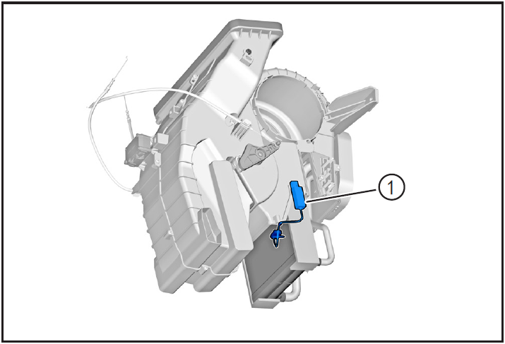
- Extract evaporator temperature sensor ① outward.
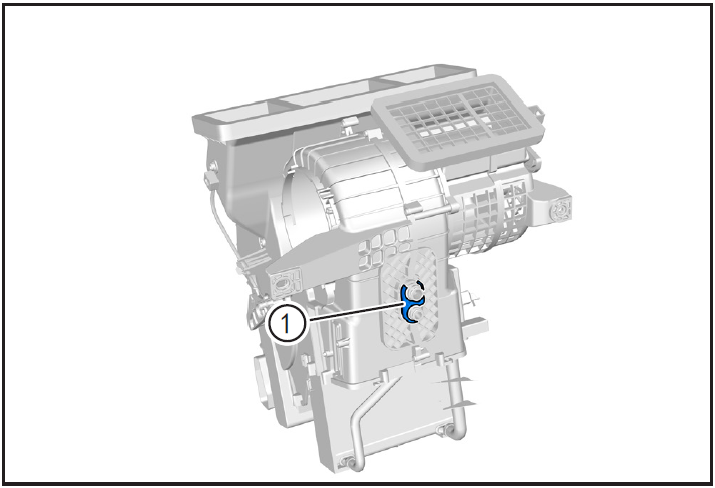
- Remove the upper limit gasket (1) of the evaporator assembly.
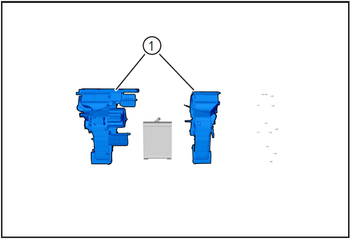
- Remove the 12 fixing screws of the air-conditioning box assembly shell by using the cross lift, and separate the left and right shells of the air-conditioning box ①.
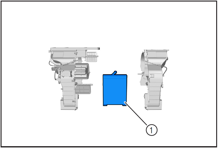
- Extract the air conditioner evaporator assembly ① outward.
6-Check
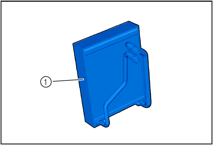
- Check the evaporator assembly ① for bumping damage, rust and leakage. Whether the blades of the evaporator assembly are deformed or not, and whether there are residues inside the core of the evaporator assembly. If yes, repair or replace the evaporator assembly with a new one.
- Check whether the evaporator assembly pipeline is damaged, and if so, replace it with a new evaporator assembly ①.
7-Installation
Installing evaporator assembly
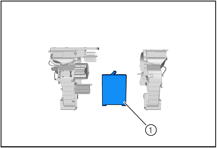
- Align the air conditioner evaporator assembly ① with the installation surface of the air conditioner shell and place it in place.

- Install the left and right shells of the air-conditioning box to ensure that the air-conditioning box assembly is installed in place.
- Install the 12 fixing screws for the air conditioning box assembly housing and tighten them using a cross lift.
注意!
- When installing the left and right shells, make sure that the damper transmission mechanism in the air conditioner shell is clamped into the installation hole on the air conditioner shell.

- Clip the gasket and retaining plate of the evaporator assembly into the initial installation position of the evaporator assembly.
- Clip the evaporator temperature sensor ① into place at the mounting hole.
注意!
- When installing the evaporator temperature sensor, pay attention to avoid damaging the heat sink of the air conditioner evaporator.

- Place the lower housing of the air conditioning box assembly to the installation position.
- Install the 8 fixing screws for the lower housing of the air conditioning box assembly and tighten them using a cross.
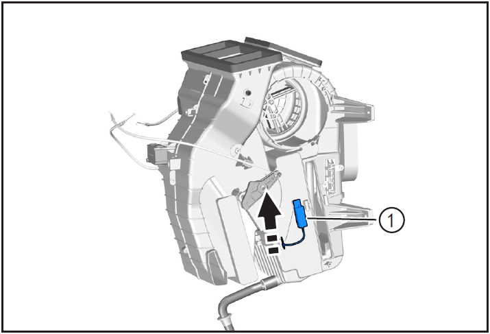
- Insert the air-conditioning evaporator temperature sensor socket card ① into the air-conditioning box assembly fixing card in the direction of the arrow.
Installing speed control module
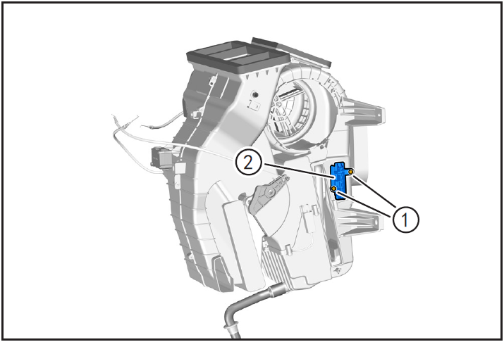
- Align the speed regulating module ① with the installation hole of the air conditioning box and install it.
- Install fixing screws ② and tighten them using cross lifting.
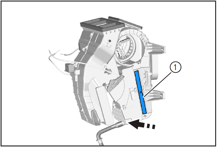
- Install air conditioner filter element ① in the direction of arrow.
注意!
- Pay attention to the installation direction of air conditioner filter element.

- Place the air conditioner filter cover ① to the installation position.
- Install the air conditioner filter cover fixing screw ② and tighten it using a cross.
Installing blower assembly
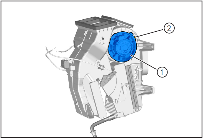
- Put the blower assembly ① to the installation position and rotate the blower assembly counterclockwise in the direction of the arrow.
- Install the blower assembly fixing screw ② and tighten it using the cross lift.
Installing air conditioning box assembly

- Install air conditioning box assembly ①. (Refer to "Removal and Installation of Air Conditioning Box Assembly" in this section)
8-Vehicle low voltage circuit unlock
- Refer to "Vehicle Low Voltage Circuit Locking and Unlocking" in the chapter "Power Battery System" for the following operation
Install battery positive and negative cables

- Install battery negative cable ① and positive cable ②.
10-Clear fault code, check
- After installation, turn the ignition switch to "ON", connect the diagnostic instrument, and clear the fault code.
- Check the air conditioning system to make sure the vehicle is running normally.
- Remove safety warning fences and warning signs.